 Latest images
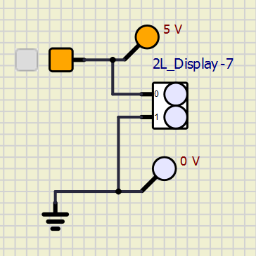
That is not how you test a subcircuit.Alex68 wrote:Из тех же инструментов в сборке R815. Модель двух разрядного индикатора. Нет индикации уровня. На всех остальных с большим числом разрядов так же.
That subcircuit is working perfectly.

![]() Message [Page 3 of 9]
Message [Page 3 of 9]
 Re: SimulIDE 1.0.0 Tester builds. Sun Jan 09, 2022 12:47 pm
That is not how you test a subcircuit.Alex68 wrote:Из тех же инструментов в сборке R815. Модель двух разрядного индикатора. Нет индикации уровня. На всех остальных с большим числом разрядов так же.
Re: SimulIDE 1.0.0 Tester builds. Sun Jan 09, 2022 3:34 pm
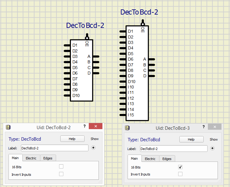
arcachofo wrote:Just move that decoder and see what happens...Например вот такое. Простая схема инструмента - формирователя импульсной последовательности с клавиатуры. В двух версиях. Может такое и с моделями контроллеров. Где то что то не пропечаталась связь и все. Работать не будет.
Please, stop talking about what you don't know.
Again: you have no idea of what you are talking about, and you are talking silly things.
This section is for testers, for people that is willing to help testing and reporting errors.
You found an error in a subcircuit and you don't report what model has the problem.
Instead you start to talk silly things about a topic you ignore completely.
Re: SimulIDE 1.0.0 Tester builds. Sun Jan 09, 2022 3:58 pmThis guy...Куда я должен перемещать этот декодер если у него внутри во первых неправильно сделан шифратор на 15. И связи от этого нарушены. Я его открыл ВАМ а вы не видите видимо.
 Re: SimulIDE 1.0.0 Tester builds. Mon Jan 10, 2022 10:21 pm
Thanks.Tried to open ATmega1281.
Re: SimulIDE 1.0.0 Tester builds. Tue Jan 11, 2022 6:39 pm Re: SimulIDE 1.0.0 Tester builds. Sat Jan 15, 2022 1:55 amFizik_S and dvarkin like this post
Re: SimulIDE 1.0.0 Tester builds. Sat Jan 15, 2022 4:34 pm Re: SimulIDE 1.0.0 Tester builds. Sat Jan 15, 2022 6:38 pm Re: SimulIDE 1.0.0 Tester builds. Sat Jan 15, 2022 7:13 pm
Ohh sorry, I will reupload.The MCUs (at least explicitly the mega328) are missing SimulIDE_1.0.0-R853_Win64..
Last edited by arcachofo on Sat Jan 15, 2022 7:25 pm; edited 1 time in total
Re: SimulIDE 1.0.0 Tester builds. Mon Jan 17, 2022 8:52 pm
 Re: SimulIDE 1.0.0 Tester builds. Mon Jan 17, 2022 9:04 pm Re: SimulIDE 1.0.0 Tester builds. Mon Jan 17, 2022 9:18 pm
Solved at Rev 862.1) encoder error when operating in 16-bit mode.
Solved at Rev 863.2) The probes are not working correctly.
Fizik_S likes this post
Re: SimulIDE 1.0.0 Tester builds. Mon Jan 17, 2022 9:20 pmCan you explain this issue?I also had a similar kind of "not correctly working visible output" issue when using mulitple 7-segment displays driven by a MCU with the R853 / WIN10 . There it seems to be connected to the simu speed.
Re: SimulIDE 1.0.0 Tester builds. Mon Jan 17, 2022 9:47 pmI also had a similar kind of "not correctly working visible output" issue when using mulitple 7-segment displays driven by a MCU with the R853 / WIN10 . There it seems to be connected to the simu speed.
Re: SimulIDE 1.0.0 Tester builds. Tue Jan 18, 2022 2:10 am bugs_tf.zip Re: SimulIDE 1.0.0 Tester builds. Tue Jan 18, 2022 3:29 am
(without any direct connection have to think on famous dilbert Very Happy ):
 Re: SimulIDE 1.0.0 Tester builds. Tue Jan 18, 2022 3:35 am Re: SimulIDE 1.0.0 Tester builds. Tue Jan 18, 2022 8:18 am
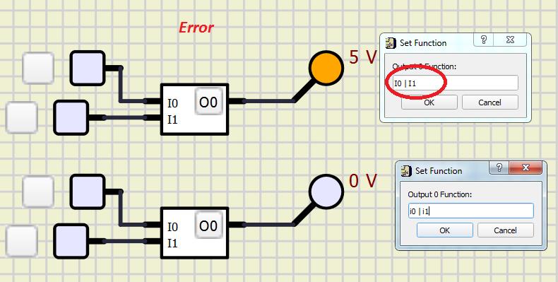 Re: SimulIDE 1.0.0 Tester builds. Tue Jan 18, 2022 7:03 pm
Thanks. Solved at Rev 864.The logical primitive "Function" allows only lowercase letters in logical formulas (i 0, i 1, ...). When using capital letters in a formula (I 0, I 1, ...), "Function" does not work correctly.
Fizik_S likes this post
Re: SimulIDE 1.0.0 Tester builds. Tue Jan 18, 2022 10:51 pm Re: SimulIDE 1.0.0 Tester builds. Wed Jan 19, 2022 8:21 am
 uint8_t numberToOutput = 0;
 uint8_t sevenSegmentPos = 0;


int main()
{
 TCCR0A  = 0; // Timer 0 auf "Normal Mode" schalten
 SET_BIT(TCCR0B,CS10); // mit Prescaler 8 betreiben
 SET_BIT(TIMSK0,TOIE0); // Overflow-Interrpt aktivieren

 DDRD=0xff;
 DDRB=0xff;

 sei();

 while(1)
 {
 if (flag)
 {
 flag=0;
 numberToOutput = sevenSegmentPos;

 PORTD = 0;
 PORTB = 0;

 DDRC  = sevenSegmentOutput[2][sevenSegmentPos]; // sets used Common Cathode
 PORTD = sevenSegmentOutput[0][numberToOutput];  // PORTD and PORTB writes a..g of 7-Segment-Display
 PORTB = sevenSegmentOutput[1][numberToOutput];  //

 if (++sevenSegmentPos > 3) sevenSegmentPos = 0;
 }
 }
 return 0;
}

ISR (TIMER0_OVF_vect)
{
 flag = 1;
}
Yes, there are several problems.The cofiguration as input was my fault. Initially the students used DDRB and DDRD correctly. But even with DDRB = 0xFF and DDRD = 0xFF the circuit behaves unusual: the simulation crashes for "normal" speeds
Indeed the "ugly" version is the good one to find the problem:It initially started with a program like the following, where an interrupt is initiating the refresh. This is not as ugly (and ugly behaving) as the first code and works also with the diodes in the linear range and higher currents.
![]() Message [Page 3 of 9]
Message [Page 3 of 9]
Similar topics
![]()
Permissions in this forum:
You cannot reply to topics in this forum
|
|
|


