 Latest images
The author of this scheme is trying to make a controller model. Therefore, he marked the name of the chip's pins with tunnels. I also do this (for example, in the TL431 chip).

SimulIDE 1.0.0 Tester builds.
+6
TimFisch
dvarkin
Fizik_S
MSABU
Alex68
arcachofo
10 posters
![]() Message [Page 6 of 9]
Message [Page 6 of 9]
127 Re: SimulIDE 1.0.0 Tester builds. Thu Mar 24, 2022 2:13 am
arcachofo

Oh... I understand.The author of this scheme is trying to make a controller model. Therefore, he marked the name of the chip's pins with tunnels. I also do this (for example, in the TL431 chip).
What caught my atention is the fact that he is not using the Tunnel "Id" but the "Label".
If these are to connect to the package it does not affect the circuit behavior, but at some point he will need to set the "Id" property, which is an aditional work.
128 Re: SimulIDE 1.0.0 Tester builds. Thu Mar 24, 2022 6:45 am
Fizik_S

I didn't pay attention to the error with the labels. This is a small problem. The main task is to localize the error that slows down the development of the model.
There are also errors in the PIC16F886 simulation. The scheme (post 107 in this topic) works correctly on version 0.4.15. In version 1.0.0 R999, a stable error appears: after pressing one of the control buttons (Play, Rew, FF), the operation stops after a few seconds. In version 1.0.0 RC2, the error manifests itself in different ways: 1) there is no reaction to pressing the buttons, 2) the error appears as in version R999, 3) the activated command cannot be stopped by pressing the Stop button. I did not find any patterns in the manifestation of errors. A little later I'll try to use the debugger. But there may be difficulties with this: I do not know the PIC assembler even at the initial level. I can only approximately localize the place with the error.
There are also errors in the PIC16F886 simulation. The scheme (post 107 in this topic) works correctly on version 0.4.15. In version 1.0.0 R999, a stable error appears: after pressing one of the control buttons (Play, Rew, FF), the operation stops after a few seconds. In version 1.0.0 RC2, the error manifests itself in different ways: 1) there is no reaction to pressing the buttons, 2) the error appears as in version R999, 3) the activated command cannot be stopped by pressing the Stop button. I did not find any patterns in the manifestation of errors. A little later I'll try to use the debugger. But there may be difficulties with this: I do not know the PIC assembler even at the initial level. I can only approximately localize the place with the error.
129 Re: SimulIDE 1.0.0 Tester builds. Thu Mar 24, 2022 8:11 am
arcachofo
Yes of course.The main task is to localize the error that slows down the development of the model.
And PIC simulation still need lot of work and testing.
Solved at Rev 1023.1) there is no reaction to pressing the buttons
I don't undertand this one.3) the activated command cannot be stopped by pressing the Stop button.
After solving 1), when I press "Play" the motor spins for aproximately 1 second and stops by itself.
I don't know how to do for continuous play.
If I set the simulation speed very slow then I can stop after pressing Play.
So stop button is also working.
130 Re: SimulIDE 1.0.0 Tester builds. Thu Mar 24, 2022 11:18 am
Fizik_S
After solving 1), when I press "Play" the motor spins for aproximately 1 second and stops by itself.
I don't know how to do for continuous play.
I compared the simulation of the circuit in version 0.4.15 and 1.0.0. In the program version 0.4.15, the movement of the motors does not stop after 1 second and continues until the Stop button is pressed. If you turn off the Break switch, the movement of the motors stops after 1 second. That is, if no pulses with a frequency of 68.560 HZ are received at the input B3 of the microcontroller, the program turns off the motors (the tape recorder hitchhikes when the tape ends in the cassette). Therefore, I can assume that the problem is in the part of the program that responds to the signal from port B3. This port, if I understand correctly, causes an interrupt. Perhaps the reason for the error is incorrect interrupt handling. Perhaps the reason for the error is incorrect interrupt handling. The interrupt handler is in the program from line 133.
131 Re: SimulIDE 1.0.0 Tester builds. Thu Mar 24, 2022 1:18 pm
arcachofo
Currently, even after solving 1) it stops after 1 second with Break switch open or closed.If you turn off the Break switch, the movement of the motors stops after 1 second.
So this is another problem.
Thanks, that is good information.Perhaps the reason for the error is incorrect interrupt handling. The interrupt handler is in the program from line 133.
132 Re: SimulIDE 1.0.0 Tester builds. Thu Mar 24, 2022 6:36 pm
Fizik_S
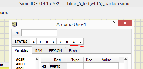
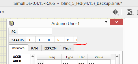
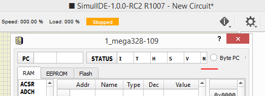
The MCU monitor does not display the lower bits of the status register in versions 1.0.0 RC2, 0.4.15 R266, 0.4.15 R271
133 Re: SimulIDE 1.0.0 Tester builds. Fri Mar 25, 2022 9:56 am
arcachofo
Solved at Rev 1029.The MCU monitor does not display the lower bits of the status register in versions 1.0.0 RC2, 0.4.15 R266, 0.4.15 R271
134 Re: SimulIDE 1.0.0 Tester builds. Sun Mar 27, 2022 12:19 pm
arcachofo
Solved at Rev 1041.the movement of the motors stops after 1 second, with Break switch open or closed.
Fizik_S likes this post
135 Re: SimulIDE 1.0.0 Tester builds. Fri Jul 01, 2022 2:34 pm
arcachofo
New build at Rev 1103 uploaded.
Have a look at first post for download links and list of changes.
Remember that this is version 1.0.0, candidate for next "stable" version, not the development version with last changes and features.
Have a look at first post for download links and list of changes.
Remember that this is version 1.0.0, candidate for next "stable" version, not the development version with last changes and features.
136 Re: SimulIDE 1.0.0 Tester builds. Sat Jul 02, 2022 5:54 am
TimFisch

I found a bug in the 1.0.0 R1103 / 1.0.1 R1279:
The I2C to parallel component acts strange, when used as a sending slave: I combined it with an ADC and tried to get all date via I2C. For analog values larger than 2.5 (= digital values with D7 set) everything works fine. For smaller values the TWSTO seems not to be set.
In the example, the (external) ADC value can be seen also in PORTB (via the MCU monitor) as a check.
https://wiki.mexle.org/_media/i2c_bug.zip
137 Re: SimulIDE 1.0.0 Tester builds. Sat Jul 02, 2022 6:25 am
TimFisch
Is the SPI module of 1.0.0 the same like the one of 1.0.1 R1279?
The following link leads to a (rough coded) SPI example, where a WS2812 matrix shall be refereshed by a slave (random equalizer LEDs). The 1.0.1 R1279 does this fine, but the 1.0.0 seems to have some trouble with the SPI...
https://wiki.mexle.org/_media/student_example_spi.zip
Additionally, the SimulIDE WS2812 seems to have more strict timing tolerances compared to the reality. This lead to some problems with the existing c libs (expecially the timing)
The tolerances are given here:
https://cdn-shop.adafruit.com/datasheets/WS2812.pdf#page=3
A "non-working" timing is e.g. in the following lib (whihch works in reality):
https://github.com/cpldcpu/light_ws2812/blob/master/light_ws2812_AVR/Light_WS2812/light_ws2812.c
138 Re: SimulIDE 1.0.0 Tester builds. Sat Jul 02, 2022 11:29 am
arcachofo
Thank you for testing this version.
But in other places these 2 versions have diverged quite a bit.
Seems like master atmega keeps CLK as input, but datasheet says that CLK direction must be defined by the user.
So, as far as I understand this firmware should not work: CLK pin always Low.
I'm having a look to I2C to Parallel and WS2812.
SPI module is basically identical.Is the SPI module of 1.0.0 the same like the one of 1.0.1 R1279?
But in other places these 2 versions have diverged quite a bit.
Indeed I would say that the problem is in 1.0.1:The following link leads to a (rough coded) SPI example, where a WS2812 matrix shall be refereshed by a slave (random equalizer LEDs). The 1.0.1 R1279 does this fine, but the 1.0.0 seems to have some trouble with the SPI...
Seems like master atmega keeps CLK as input, but datasheet says that CLK direction must be defined by the user.
So, as far as I understand this firmware should not work: CLK pin always Low.
I'm having a look to I2C to Parallel and WS2812.
139 Re: SimulIDE 1.0.0 Tester builds. Sat Jul 02, 2022 4:40 pm
arcachofo
About WS2812:
The library you linked seems to produce timings out of specifications, at least in the simulation:
T1H = 875 ns, while specification = 700 +-150 ns.
In the library T1H is defined at 900 ns, which it does well but is out of specifications:
Not sure why it's defined like this.
In any case if it works in a real device it should (ideally) work in the simulation.
The problem is: how do we know which are the actual tolerances in a real device?
There is a clue in the library:
Then what the component should do?
Perhaps:
- Measure the length of the total pulse.
- Check that this length is within specifications.
- If duty > 50% then it is a 1 (even if it is out of specifications)
else if duty > "minimum duty for 0" it is a 0.
The library you linked seems to produce timings out of specifications, at least in the simulation:
T1H = 875 ns, while specification = 700 +-150 ns.
In the library T1H is defined at 900 ns, which it does well but is out of specifications:
// Timing in ns
#define w_zeropulse 350
#define w_onepulse 900
#define w_totalperiod 1250
Not sure why it's defined like this.
In any case if it works in a real device it should (ideally) work in the simulation.
The problem is: how do we know which are the actual tolerances in a real device?
There is a clue in the library:
// The only critical timing parameter is the minimum pulse length of the "0"
// Warn or throw error if this timing can not be met with current F_CPU settings.
#define w_lowtime ((w1_nops+w_fixedlow)*1000000)/(F_CPU/1000)
#if w_lowtime>550
#error "Light_ws2812: Sorry, the clock speed is too low. Did you set F_CPU correctly?"
#elif w_lowtime>450
#warning "Light_ws2812: The timing is critical and may only work on WS2812B, not on WS2812(S)."
#warning "Please consider a higher clockspeed, if possible"
#endif
Then what the component should do?
Perhaps:
- Measure the length of the total pulse.
- Check that this length is within specifications.
- If duty > 50% then it is a 1 (even if it is out of specifications)
else if duty > "minimum duty for 0" it is a 0.
140 Re: SimulIDE 1.0.0 Tester builds. Sat Jul 02, 2022 7:22 pm
arcachofo
Not 100% sure about this...TimFisch wrote:The I2C to parallel component acts strange, when used as a sending slave: I combined it with an ADC and tried to get all date via I2C. For analog values larger than 2.5 (= digital values with D7 set) everything works fine. For smaller values the TWSTO seems not to be set.
Seems that the cause of the problem is that Master is sending ACK before Stop, when I think it shouldn't:
If Master sends ACK, then Slave understand that it should keep sending data.
If it happens that the first bit is 0, it will pull down SDA preventing it to rise when Master tries to generate an Stop.
But without the source code I'm not sure that Master is actually sending ACK or there is some other issue.
But the fact is that Slave thinks that an ACK is received, so it keeps sending data.
141 Re: SimulIDE 1.0.0 Tester builds. Sat Jul 02, 2022 7:53 pm
arcachofo
I found where this issue come from.arcachofo wrote:About WS2812:
The library you linked seems to produce timings out of specifications, at least in the simulation:
T1H = 875 ns, while specification = 700 +-150 ns.
In the library T1H is defined at 900 ns, which it does well but is out of specifications:
There is an WS2812B, that has different timings.
And there are different values depending on the datasheet "version".
In any case using 900 ns for WS2812 (without "B") doesn't seem correct to me.
Even if it works in a real device, which I'm not sure...
Does this library work in a real WS2812 or WS2812B??
This one has T1H 900 ns:

_____________________________________________________________
_____________________________________________________________
This one has T1H 800 ns:

142 Re: SimulIDE 1.0.0 Tester builds. Sun Jul 03, 2022 11:38 pm
TimFisch
Sorry for the delay: YEs, there are more than one WS2812.
Indeed we used the WS2812B. There are some additional WS2812-like LED-ICs:
Some (or at least one) of them had a different color coding.
Would be great to support at least WS2812, WS2812b and the SK6812 in longterm .
.
EDIT: I think one issue might also be, that the WS2812b seems more tolerant to a delay between the 24bit packets. So, when the 24th bit has a longer low voltage time (but below RES time) it seems still to work.
Indeed we used the WS2812B. There are some additional WS2812-like LED-ICs:
- WS2811 (= only the mircocontroller, so the LEDs are separate)
- WS2813 (seems to be a newer version)
- SK6812
Some (or at least one) of them had a different color coding.
Would be great to support at least WS2812, WS2812b and the SK6812 in longterm
EDIT: I think one issue might also be, that the WS2812b seems more tolerant to a delay between the 24bit packets. So, when the 24th bit has a longer low voltage time (but below RES time) it seems still to work.
143 Re: SimulIDE 1.0.0 Tester builds. Mon Jul 04, 2022 2:23 am
TimFisch
For the SPI issue you are right: the SPI CLK has do be defined manually as output pin - and it wasn't in the example...
The same is true for the I2C..
The code was not sending the NACK. with sending the NACK it works fine.
Sorry for the alarm..
The same is true for the I2C..
The code was not sending the NACK. with sending the NACK it works fine.
Sorry for the alarm..
144 Re: SimulIDE 1.0.0 Tester builds. Mon Jul 04, 2022 10:31 am
arcachofo
That is exactly what I was thinking:Would be great to support at least WS2812, WS2812b and the SK6812 in longterm
Add the possibility to choose model, in a similar way than DHT22/11.
It's easy to add all models that use the same protocol and only differ in timing.
This problem is not easy to solve.EDIT: I think one issue might also be, that the WS2812b seems more tolerant to a delay between the 24bit packets. So, when the 24th bit has a longer low voltage time (but below RES time) it seems still to work.
Specifications determine some limits within the device is guaranteed to work, but the real characteristics of the device are unknown.
The only way to do a simulation close to reality is knowing how the device actually works.
I don't think a real WS2812 measures all times and check if everything is correct.
Most probably it measures input voltage some time after a rising edge and that is all.
Then if it does not "see" another rising edge within certain time, it goes idle and ignores everything until next reset pulse.
But this is just a guess, and actual times might depend on working voltages and other factors, or can vary between brands or even single devices due to component quality, tolerance and whatever.
Some testing could determine the real characteristics of one concrete device, but that is not guaranteed to be the real characteristics of all devices of all brands.
Then... we must assume that a device in the simulation will not work exactly the same than reality.
But 2 real devices will not work exactly the same as well.
I tend to think that the best aproach is to stick to specifications and add a bit of tolerance.
This way if it works in the simulator it is guaranteed to work in reality.
If it doesn't work in the simulator it means that it is out of specifications... it might work in (some) real devices or not.
It is always good to know that the simulation does not work when it shouldn't.Sorry for the alarm..
And indeed the SPI CLK was working when it shouldn't, so that was an error (solved at Rev 1289).
TimFisch likes this post
145 Re: SimulIDE 1.0.0 Tester builds. Fri Oct 07, 2022 8:20 pm
arcachofo
New build at Rev 1145 uploaded.
Have a look at first post for download links and list of changes.
Have a look at first post for download links and list of changes.
146 Re: SimulIDE 1.0.0 Tester builds. Fri Oct 07, 2022 10:07 pm
KerimF
arcachofo wrote:New build at Rev 1145 uploaded.
Have a look at first post for download links and list of changes.
Sorry, I couldn't find the 'list of changes'.
I downloaded the zip file.
147 Re: SimulIDE 1.0.0 Tester builds. Fri Oct 07, 2022 11:34 pm
KerimF
SimulIDE_1.0.0-R1145_Win32
Please note that, in avrasm2.xml, type="avrasm00", not "avrasm01".
Please note that, in avrasm2.xml, type="avrasm00", not "avrasm01".
148 Re: SimulIDE 1.0.0 Tester builds. Sat Oct 08, 2022 12:29 am
KerimF
SimulIDE_1.0.0-R1145_Win32
The flag EEWE in EECR doesn't reset (1 to 0) to indicate end of EE writing (typically, writing a byte takes 8.5 ms).
- Code:
SV_byte:
    OUT   EEARL, tmpHiL
    OUT   EEDR, tmpHiH
    CLI                         ; disable interrupts during timed sequence
    SBI   EECR, EEMWE           ; enable EEPROM write
    SBI   EECR, EEWE            ; start EEPROM write
    SEI                         ; re-enable interrupts

EE_wait:
    SBIC  EECR, EEWE            ; wait to end previous saving
    RJMP  EE_wait

EEiniRt:
    RET
The flag EEWE in EECR doesn't reset (1 to 0) to indicate end of EE writing (typically, writing a byte takes 8.5 ms).
149 Re: SimulIDE 1.0.0 Tester builds. Sat Oct 08, 2022 8:30 am
arcachofo
There is a problem with EERE :The flag EEWE in EECR doesn't reset (1 to 0) to indicate end of EE writing (typically, writing a byte takes 8.5 ms).
Writing to EEMWE with EERE being 1 triggers a read here:
- Code:
SBI EECR, EEMWE ; enable EEPROM write
Obviously this should not happen but not sure about the exact behavior:
EEWE is cleared by hardware when the write operation is finished.
But datasheet says nothing about clearing EERE, and code examples don't clear EERE by software.
This suggest that writing 1 to EERE triggers a read operation even if it is already 1.
The problem is that the current implementation triggers it even for SBI EECR, EEMWE...
150 Re: SimulIDE 1.0.0 Tester builds. Sat Oct 08, 2022 4:03 pm
KerimF
arcachofo wrote:There is a problem with EERE :The flag EEWE in EECR doesn't reset (1 to 0) to indicate end of EE writing (typically, writing a byte takes 8.5 ms).
Writing to EEMWE with EERE being 1 triggers a read here:
The read operation takes 4 extra cycles, so when EEWE is written it is too late...
- Code:
SBI EECR, EEMWE ; enable EEPROM write
To my knowledge, EEMWE (EEPROM Master Write Enable) has no role in reading EEPROM. So, I am not sure, I got your remark well.
Although I didn't have the idea to check that EERE is reset by hardware soon after reading the byte from EEPROM [during the 4-cycle reading instruction], I think it is the case. But I will check this by running the ATMEL Studio simulator (just to be 100% sure).
Obviously this should not happen but not sure about the exact behavior:
EEWE is cleared by hardware when the write operation is finished.
But datasheet says nothing about clearing EERE, and code examples don't clear EERE by software.
This suggest that writing 1 to EERE triggers a read operation even if it is already 1.
The problem is that the current implementation triggers it even for SBI EECR, EEMWE...
I think we have here two separate processes:
For reading:
- Code:
   SBI   EECR, EERE
   IN    tmpHiH, EEDR
During the write operation (when EEWE=1), setting EERE is ignored.
For writing:
- Code:
   SBI   EECR, EEMWE           ; enable EEPROM write
   SBI   EECR, EEWE            ; start EEPROM write
EEMWE will be cleared by hardware after 4 cycles (SBI takes 1 cycle of them). Then EEWE will be cleared after 8.5 ms (and the byte of interest on EE is updated/written).
![]() Message [Page 6 of 9]
Message [Page 6 of 9]
Similar topics
![]()
Permissions in this forum:
You cannot reply to topics in this forum