 Latest images
You are creating a good collection of circuits that will be very useful for testing.
Thanks for sharing.
Thanks for sharing.

![]() Message [Page 2 of 2]
Message [Page 2 of 2]
 Re: Opamp and Trafo circuit. Thu Apr 22, 2021 2:41 am
 Re: Opamp and Trafo circuit. Thu Apr 22, 2021 6:55 am
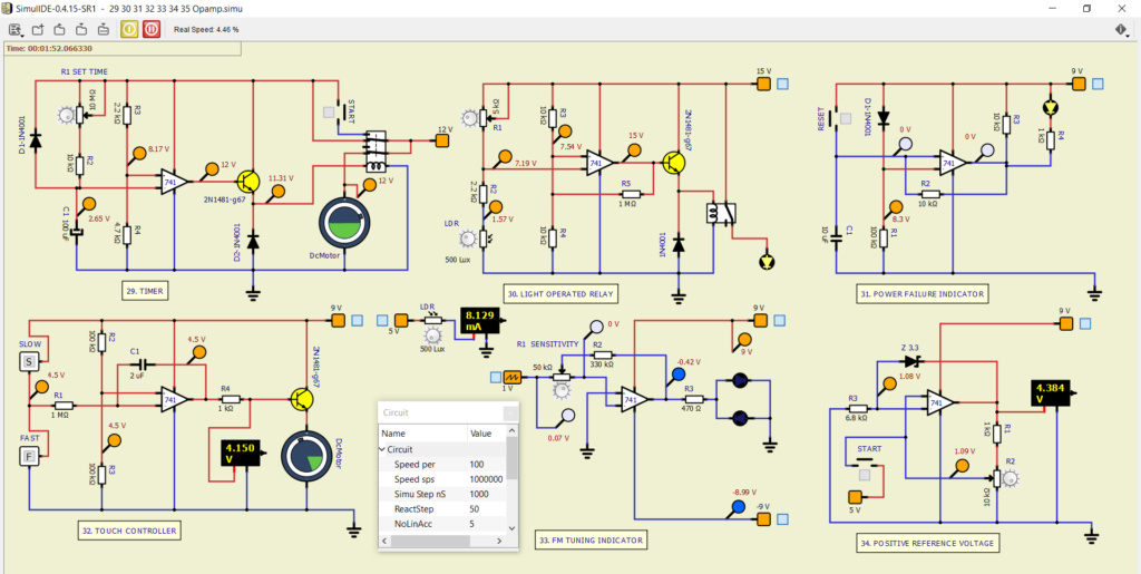
Last edited by Mistral on Thu Apr 22, 2021 7:10 am; edited 1 time in total (Reason for editing : Ps)
Re: Opamp and Trafo circuit. Fri Apr 23, 2021 1:06 pm Re: Opamp and Trafo circuit. Fri Apr 23, 2021 1:44 pm
Mistral likes this post
Re: Opamp and Trafo circuit. Fri Apr 23, 2021 7:12 pm Re: Opamp and Trafo circuit. Sat Apr 24, 2021 8:23 am
arcachofo wrote:I added transformer to the list:
https://simulide.forumotion.com/t4-list-of-feature-requests
Last edited by Mistral on Sat Apr 24, 2021 3:54 pm; edited 2 times in total
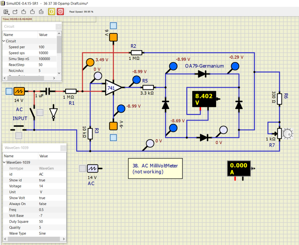
Re: Opamp and Trafo circuit. Sat Apr 24, 2021 3:40 pmCan you explain what is the problem you found?I tried to make no. 38 AC Millivoltmeter. Used different set-ups like wave generator with voltbase +5V and Volt -10, two generators, one generator with inverted buffer, etc. with no result. This is not intended to ask to 'fix' this simulation but only to make a little bit clear why I made my request.
Re: Opamp and Trafo circuit. Sat Apr 24, 2021 5:37 pm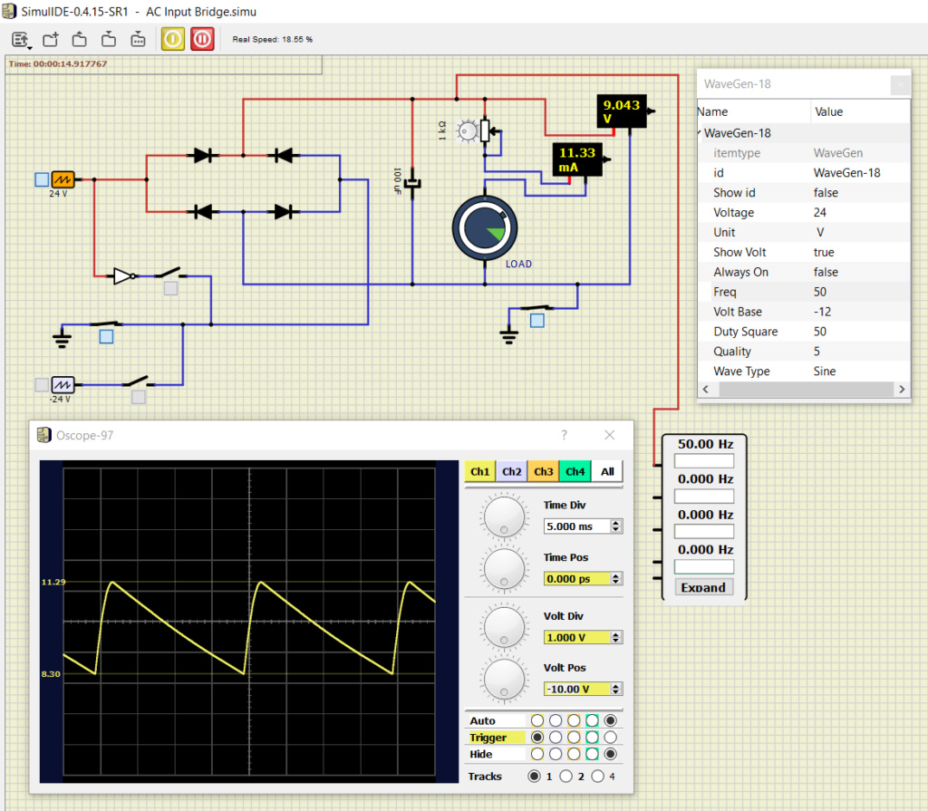
 Re: Opamp and Trafo circuit. Sun Apr 25, 2021 6:36 am
 Re: Opamp and Trafo circuit. Sun Apr 25, 2021 1:03 pm
 Re: Opamp and Trafo circuit. Sun Apr 25, 2021 3:27 pm
 Re: Opamp and Trafo circuit. Wed Jan 26, 2022 6:53 pm
arcachofo wrote:Ok, now I understand. Thanks for explaining.
Simulide has almost no support for AC, this is something that needs to be addressed.
And I would not use it for AC.
But you can trick it, for example to get an AC signal you can use 2 Wave generators.
One from 0V to 12V and the other form -12V to 0V.
You can set the property "Always On" to ensure they are in phase.
This is a similar approach as using 2 rails instead of one battery:
 Re: Opamp and Trafo circuit. Thu Jan 27, 2022 5:43 am
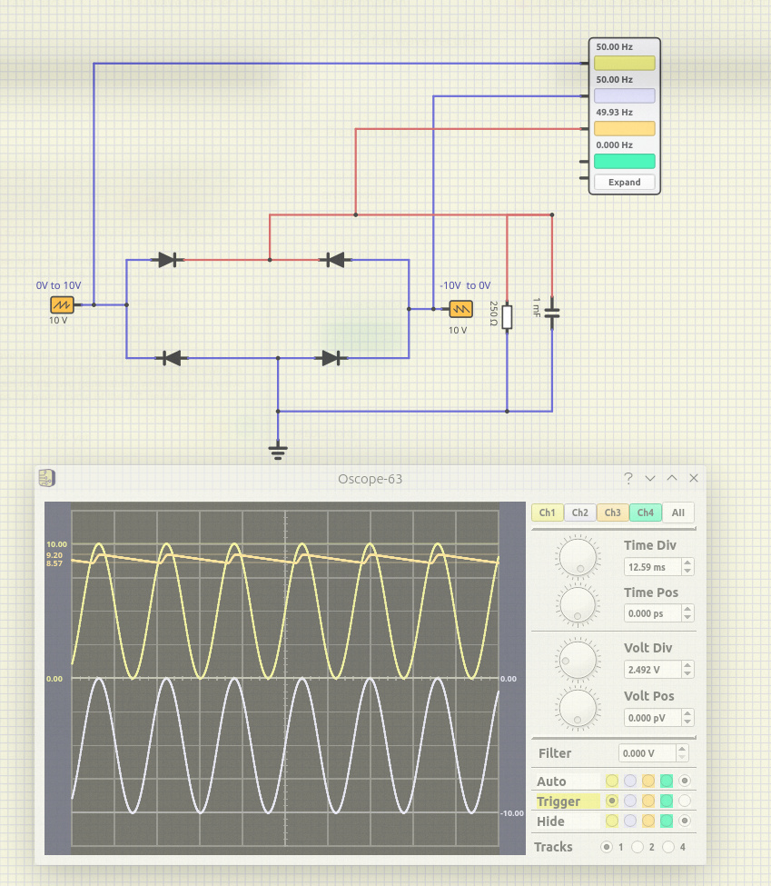
You are right.I attempted to simulate a full-wave rectifier with the suggested trick, but I am not getting the expected result: the voltage measured on the resistor is showing a ripple with the same frequency set for the two generators, while on a full-wave rectifier we should get two ripples for every cycle of the AC generator
 Re: Opamp and Trafo circuit. Thu Jan 27, 2022 2:44 pm
arcachofo wrote:
But doing some tests I found that there is an error is Oscilloscopoe component (0.4.15 and 1.0.0).
Also in 0.4.15-SR9 the Diode is very slow.
I fixed these issues and now is working as it should.
This is 1.0.0 (note that you need 2 oscilloscopes):
Re: Opamp and Trafo circuit. Thu Jan 27, 2022 4:24 pmYes, I think it is ime for a new RC, maybe in 1 or 2 weeks.do you plan to provide a new release candidate for the ver. 1.0.0 any time soon?
![]() Message [Page 2 of 2]
Message [Page 2 of 2]
Go to page : ![]() 1, 2
1, 2
Similar topics
![]()
Permissions in this forum:
You cannot reply to topics in this forum
|
|
|

