Would you like to react to this message? Create an account in a few clicks or log in to continue.

You are not connected. Please login or register

Opamp and Trafo circuit.

4 posters

Go to page : 1, 2  Next

Go down  Message [Page 1 of 2]

1Opamp and Trafo circuit. Empty Opamp and Trafo circuit. Mon Apr 12, 2021 4:52 pm

Mistral


Hi,
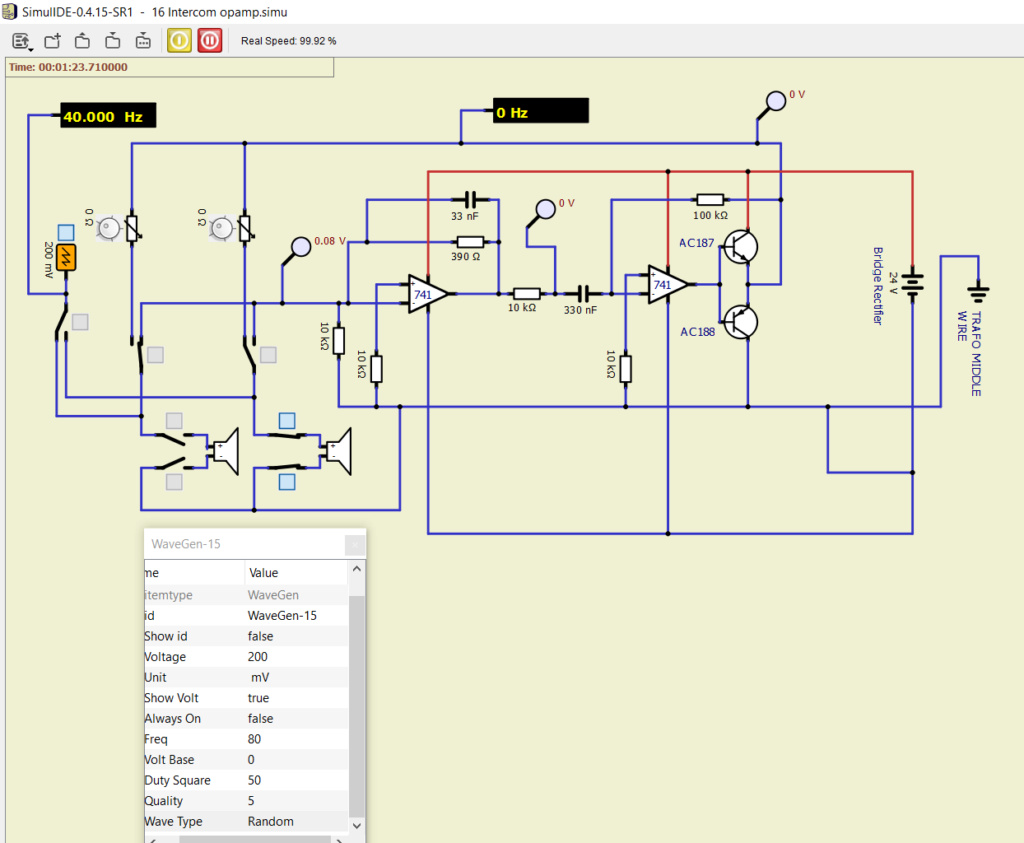
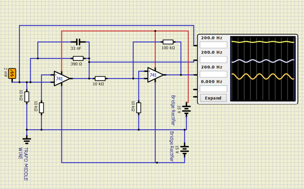
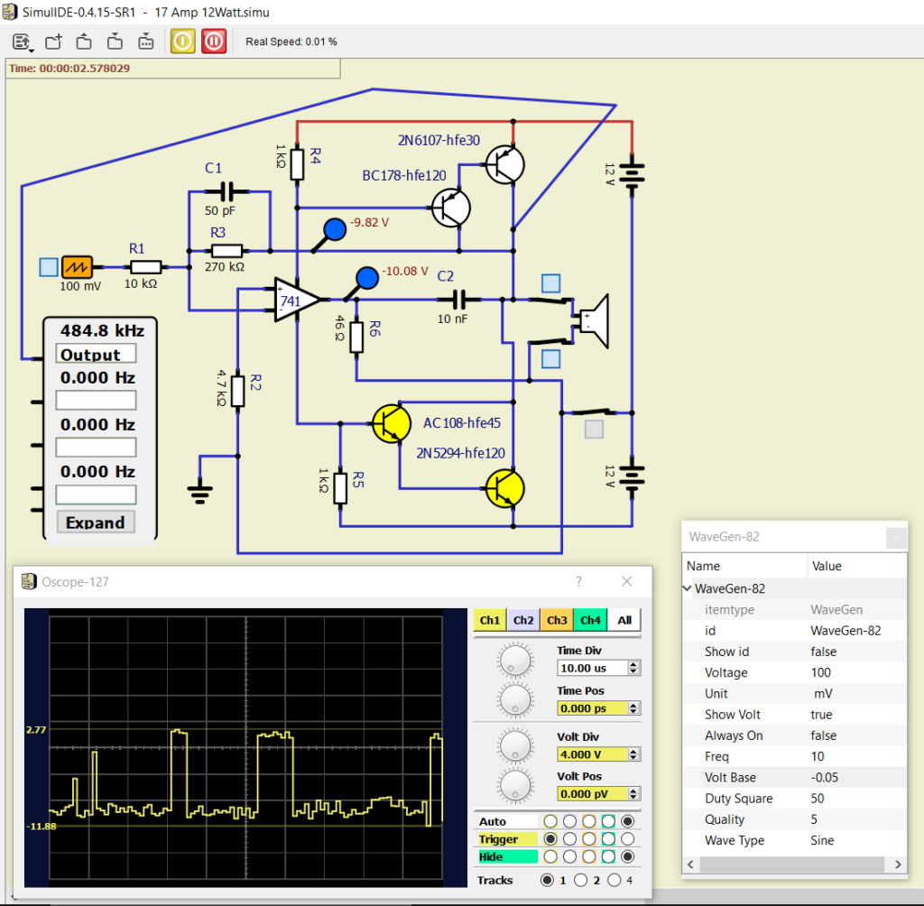
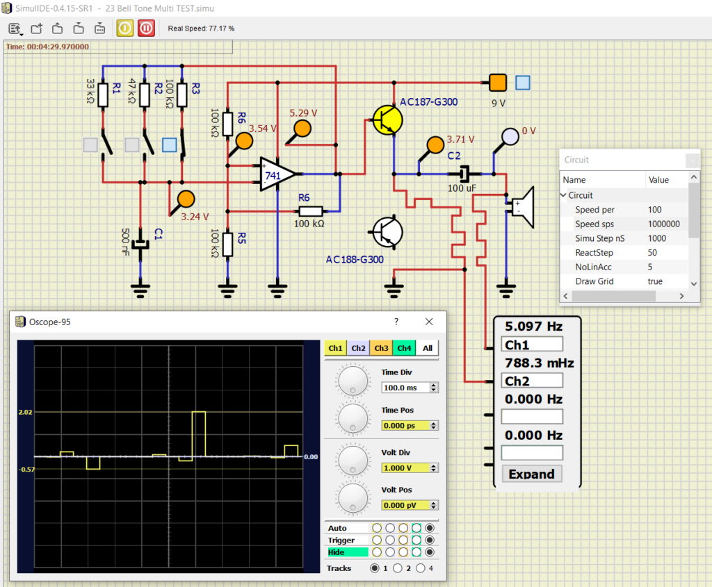
I am trying an opamp circuit, no16 on pdf page 20/42
https://diagramas.diagramasde.com/otros/41%20Projects%20using%20IC%20741%20OP-AMP.pdf

Opamp and Trafo circuit. 16_int10

Opamp and Trafo circuit. 16_int11

Speed drops to 4.5%
Volt base at 0 gives circuit error, set at e.g. 0.05 goes better.(?)
https://github.com/Alectus/Dump-sharing/blob/main/16%20Intercom%20opamp.simu


I had a more detailed post 5 minutes ago but when I pressed send it was gone: post message too long it said  Sad  I had copy/pasted the pictures in it.
Anyway, congratulations with the release of 4.15 Very Happy
And thank you all for keeping this splendid software in development.

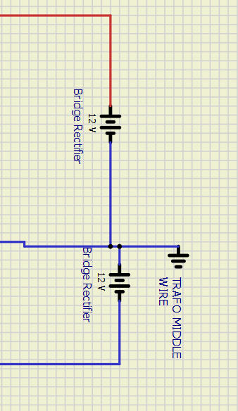
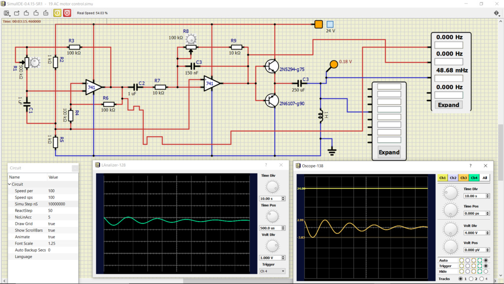
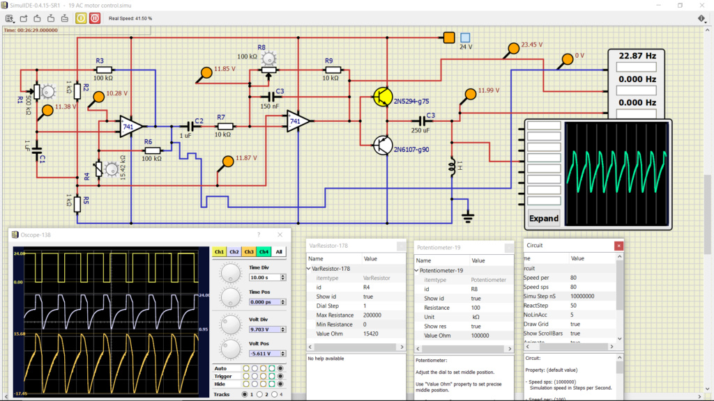
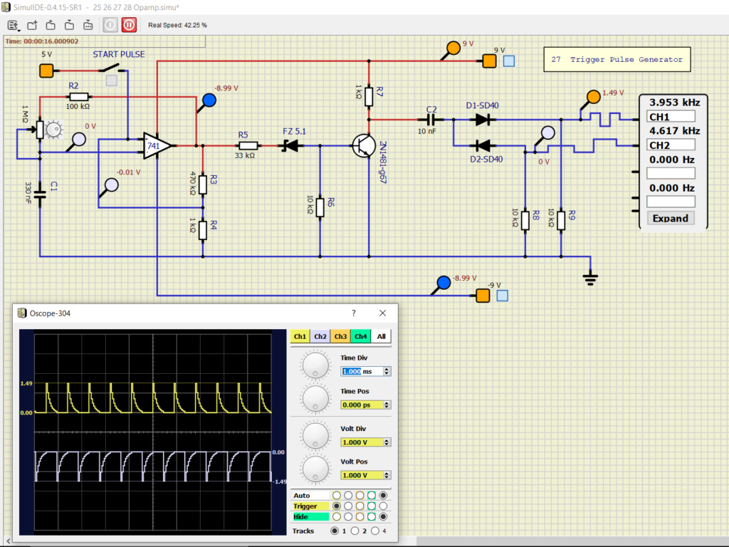
Sine wave generator is used as incoming microphone signal. The 24V battery is replacement for the trafo-bridge section and the Gnd as middle wire from the trafo. I am not taking this excercise very serious although I spent a couple hours with it. Probably I am doing something wrong but don't know another way where else to put the trafo middle wire connected to ?
https://github.com/Alectus/Dump-sharing/blob/main/16%20Intercom%20opamp.simu
And yellow flashing transistor, it does not mean it is blown up right, only that it is switching on/off fast?

2Opamp and Trafo circuit. Empty Re: Opamp and Trafo circuit. Mon Apr 12, 2021 6:19 pm

Mistral


It seems that the 'circuit error' has more to do with the Gnd than with Volt base.
I threw out the 2x 1mF caps and made a common gnd.

Opamp and Trafo circuit. 16_int12

Speed is up to 100%.
But this seems to be only when generator is set to random, not with sinus, triangle or square, then it drops back to 4.5 precent. (?)
Not much sound to hear either.

3Opamp and Trafo circuit. Empty Re: Opamp and Trafo circuit. Mon Apr 12, 2021 6:39 pm

arcachofo

arcachofo

One thing is about wave generator:
"Volt Base is" the minimum voltage, not the middle voltage.
This maybe not very intuitive, if you want an AC signal from -200 mV to 200 mV, then set "Volt Base" to -200 mV and Voltage to 400 mV.


And yellow flashing transistor, it does not mean it is blown up right, only that it is switching on/off fast?
Yes, yellow means that it is "ON"


I will test your circuit and see what i find.

Mistral likes this post

4Opamp and Trafo circuit. Empty Re: Opamp and Trafo circuit. Mon Apr 12, 2021 8:04 pm

Mistral


I will test your circuit and see what i find.


Well thanks, if you have time for it but like I said I don't take it too serious because I must admit that there is also a certain amount of lack of knowledge in play of real electronics circuit behaviour from my part, especially with these kinds with opamp and trafo's and so on.

Opamp and Trafo circuit. 16_int13

This is rather stable, the speaker ticks nicely.
Circuit error, just start a couple of times and it will catch.
And be patient, things take time to settle down when it is at very low Speed. And don't change too much at the same time, step by step adjustments, saving, sometimes save and re-open. 
Thanks for explaining Volt base, I made a note of it.

5Opamp and Trafo circuit. Empty Re: Opamp and Trafo circuit. Mon Apr 12, 2021 8:12 pm

Fizik_S

Fizik_S

Power supply connection error. You need 2 batteries of 12 volts each.
Opamp and Trafo circuit. 74110

---
I got the normal simulation speed by removing the transistors from the circuit. The input voltage must not exceed 2 millivolts. At a higher voltage, the output voltage turns from a sinusoid to a trapezoid.
Opamp and Trafo circuit. 741-110

---
The final version. I removed the frequency meters and the simulation speed increased slightly. After removing the capacitor between the operational amplifiers, the excitation at the output of the second amplifier was lost.
Opamp and Trafo circuit. 741-210

arcachofo and Mistral like this post

6Opamp and Trafo circuit. Empty Re: Opamp and Trafo circuit. Tue Apr 13, 2021 3:11 pm

Mistral


Power supply connection error. You need 2 batteries of 12 volts each.


Very good Like a Star @ heaven thank you. I recognise it when I see it but it didn't come to mind.
I'll try to keep it short. I reproduced your set-up


Opamp and Trafo circuit. 16_int14


My speed is 1/3 of yours but can have to do with my computer maybe.
I remember you advised to keep sim-circuits simplified and indeed it gives better result and also better understanding of what the circuit is about essentially. On the other hand, it is barely recognisable as the original.
The scope is a great piece of work, thank you. Opamp and Trafo circuit. 1f44d 
Minor minor remark, CH3 in red or blue would make it differ more from CH1, on my screen.

Three months ago or so I used this demo

Opamp and Trafo circuit. 16_int15
How would you draw a transformer in SimulIDE? I tried quite a lot yesterday evening.
I saw a couple of questions before about it, or related to it, one I couldn't find back yet.
https://simulide.forumotion.com/t120-is-there-a-possibility-for-an-ac-source
https://simulide.forumotion.com/t30-features-for-function-generator

7Opamp and Trafo circuit. Empty Re: Opamp and Trafo circuit. Tue Apr 13, 2021 7:51 pm

Mistral


Strange.
This is the next one, no.17 - 12W amplifier
https://diagramas.diagramasde.com/otros/41%20Projects%20using%20IC%20741%20OP-AMP.pdf
Github
https://github.com/Alectus/Dump-sharing/blob/main/17%20Amp%2012Watt.simu

Opamp and Trafo circuit. 17_amp10

The speed is at 0.01% and maybe that's why you can only hear a single tick from the speaker now and then. But strangely, despite speed at 0, the probes are flashing very fast, 
I love this new blue one flower 

and the scope is running like a freight train. How can that be?

8Opamp and Trafo circuit. Empty Re: Opamp and Trafo circuit. Tue Apr 13, 2021 9:15 pm

arcachofo

arcachofo

The speed is at 0.01% and maybe that's why you can only hear a single tick from the speaker now and then.
Simulation with non-linear and reactive components can be very slow.

Anyway this circuit does not work in simulide:
I was wondering how the output stage works in this circuit...

17. 12W Amplifier wrote:"The input signals for the Darlingtons are derived from the suply current of the 741"

The suply current is not simulated is simulide.

9Opamp and Trafo circuit. Empty Re: Opamp and Trafo circuit. Tue Apr 13, 2021 9:57 pm

Mistral


I am just playing arcachofo  Very Happy
Me myself don't know how this circuit works, to simulate it would take a lot of very difficult math I guess. Something you know much more about than me. And it is a very basic amplifier so to see. It will not produce a perfect magnification of the input signal I guess.
Anyway, managed to get the speed up to 20% without making any changes in the circuit really.
Great fun trying all those options you have put into it. Speaker still not making noise, it gave a click every real 1.5 minute in the previous and in this one it is also very silent.
Anyway, time for cerveza, see you later. Salut.

Opamp and Trafo circuit. 17_amp11
 
10.000.000 Steps/ns - How high can it go?!   Shocked
And who can guarantee that this schematic built with real components shall produce a nice sound? I didn't try it.
I am already happy thanks to Fizik that the 'circuit error' is gone, and that in itself means making progress.


Last edited by Mistral on Tue Apr 13, 2021 10:31 pm; edited 1 time in total

10Opamp and Trafo circuit. Empty Re: Opamp and Trafo circuit. Tue Apr 13, 2021 10:30 pm

arcachofo

arcachofo

Speaker still not making noise
As I said, this circuit does not work in simulide.
What you are getting is just noise, you will get the same is you turn off the wave generator.

10.000.000 Steps/ns - How high can it go?!
This porpety system is not very intuitive (in 0.5 it will be better).
"Simu Step ns" is the size of a simulation step in nanoseconds.
In this case simulation step will be 10 ms.
So the bigger it is the faster the simulation, but you can miss anything that is shorter than that.

11Opamp and Trafo circuit. Empty Re: Opamp and Trafo circuit. Tue Apr 13, 2021 10:43 pm

Mistral


What you are getting is just noise, you will get the same if you turn off the wave generator.


Yes, I noticed that. And it is when you turn on the gen the speed starts dropping steeply at the normal default settings. Anyway, I am a little bit done with Cpu's, I, or better said, we made 5 already - the ben eater, the gigatron, the nibbler, the mk4 and the Gep. Three or maybe even four of them where imo very succesfull reproduced by Simulde, and besides, there seem not to be many more projects like those on the internet.
I didn't jump into these opamps at example 16, I started at no. 1 four months ago. Making the drawings is in itself helpfull to better understand this specific electronics.

12Opamp and Trafo circuit. Empty Re: Opamp and Trafo circuit. Wed Apr 14, 2021 7:40 pm

Mistral


No.18 is doing perfectly. Only difference: no caps and no generator. 
Full speed 99.9% at default settings.
https://github.com/Alectus/Dump-sharing/blob/main/18%20DC%20motor%20control.simu

Opamp and Trafo circuit. 18_dc_10

Pdf page 22/42
https://diagramas.diagramasde.com/otros/41%20Projects%20using%20IC%20741%20OP-AMP.pdf

So what is causing the difficulty in the previous - only the wave generator, only the caps or both in a  combined configuration?

13Opamp and Trafo circuit. Empty Re: Opamp and Trafo circuit. Wed Apr 14, 2021 9:42 pm

arcachofo

arcachofo

So what is causing the difficulty in the previous

Because:

"The input signals for the Darlingtons are derived from the suply current of the 741"

And the suply current is not simulated is simulide.
So there is no input signal for the Darlingtons.


In adition:
"An overall dc negative feedback from the common collector junction of T2 and T4 stabilises the dc conditions of the circuit..."

Without that negative feedback all you get is noise.

14Opamp and Trafo circuit. Empty Re: Opamp and Trafo circuit. Wed Apr 14, 2021 11:49 pm

Mistral


Thanks a lot, sorry you had to repeat yourself, sometimes I'm a bit slow  silent 
I am doing no19 now. At first as soon as I switched the 24V on speed dropped immediately to 0.01%
But there is no noise at start up. When the 24V is switched off it keeps oscillating.
Anyway, I've set the Step ns to 10 million and it is very interactive. There is no AC motor available and dropped a 1H inductor there. No idea if this comes close but the circuit is alive and kicking.  Cool
I was afraid that none of the opamp examples where simulatable but I understand now that only in specific cases it is not do able. Well, that's a releave.

Opamp and Trafo circuit. 19_ac_10

https://github.com/Alectus/Dump-sharing/blob/main/19%20AC%20motor%20control.simu

Ps, I just reopend it and all my speed setting were gone, it took some strange values. Maybe it's only this time and not structural I hope.

I have it oscillating now. Replaced R4 with a 0-200K variabele resistor. 

Opamp and Trafo circuit. 19_ac_13

There has to be some speed so you can see changes and start experimenting and understanding what a circuit does. When there is no speed at all you might just as well be looking at a painting.
This picture is taken after 15 minutes without making any adjustments what so ever and it is running completely by itself. Great software! Thank you.  Like a Star @ heaven

Setting C1 to 0.1 uF makes it run a lot faster and R1 becomes more usefull and in range as frequency controller. I noticed there is no variable capacitor. I know it is already variable by its properties but it would be a nice extra feature  Wink

15Opamp and Trafo circuit. Empty Re: Opamp and Trafo circuit. Thu Apr 15, 2021 12:36 pm

Mistral


It happened again what I mentioned in previous post. After re-opening these are the central panel properties

Opamp and Trafo circuit. Speed_11

And in the oscope text-fields where you can write your own comment, like Ch1 or Input, most of the times when you do a backspace or del the whole oscope disappears.
Maybe I should have posted this in the report bugs-section? Feel free to move or copy it.  Opamp and Trafo circuit. A9 

So far I have not seen a Pnp turn yellow.

16Opamp and Trafo circuit. Empty Re: Opamp and Trafo circuit. Thu Apr 15, 2021 3:11 pm

Mistral


Trying Pnp
https://learn.sparkfun.com/tutorials/transistors/applications-i-switches
Npn motor is going good but as soon as the 12V switch of Pnp is turned on Speed drops to 0.0%
This is not happening in 4.14, there both motors can be switched on or off as expected. 
Edit: 4.14 is showing strange behaviour now but Speed stays stable.
https://github.com/Alectus/Dump-sharing/blob/main/PNP%20Yellow.simu

Opamp and Trafo circuit. Pnp_ye10

This circuit is drawn in 4.15, then also opened in 4.14.
Central panel properties are at default.
I hope I am not wasting your time because I made a stupid mistake or something.

17Opamp and Trafo circuit. Empty Re: Opamp and Trafo circuit. Thu Apr 15, 2021 8:19 pm

arcachofo

arcachofo

I hope I am not wasting your time because I made a stupid mistake or something.
That is not a problem, it is much better reporting a possible issue that ends up being a mistake than not reporting.

I will have a loook.

18Opamp and Trafo circuit. Empty Re: Opamp and Trafo circuit. Fri Apr 16, 2021 3:01 am

Mistral


4.14 Motor is spinning on one leg wire 

Opamp and Trafo circuit. Pnp_dc10

19Opamp and Trafo circuit. Empty Re: Opamp and Trafo circuit. Fri Apr 16, 2021 9:10 pm

arcachofo

arcachofo

4.14 Motor is spinning on one leg wire
This is solved in 0.4.15

And yersterday I solved some other minor issue.

I'm still working in the pnp bjt issue.

Mistral likes this post

20Opamp and Trafo circuit. Empty Re: Opamp and Trafo circuit. Mon Apr 19, 2021 3:43 am

arcachofo

arcachofo

Circuit speed error solved in Rev 154.
PNP not working solved in Rev 155.

Oscope dissapears with backspace or del, still needs a solution.
By now, be sure nothing is selected before editing those text-fields.

21Opamp and Trafo circuit. Empty Re: Opamp and Trafo circuit. Tue Apr 20, 2021 10:38 am

Mistral


Ok, tnx. Not sure what you mean by Rev 155, the next revision of course and I suppose it will be in the next 0.4.15 Stable SR1 release? And I conclude the bug is more than just the replacement of the PNP-BJT package?
And I don't understand good if you look at my post no.14 the second picture it gives a very nice scope view. One would not say there is something wrong with the PNP. Yes, I reported it myself in reply16 so also according to me there is something not quite right but in this circuit it seems to be functioning. Or am I missing something?

Today I compared a same kind of NPN-PNP pair in both 4.14 and 4.15 and the scope views are similar. They both show a block and another shape that I don't know the name for. Anyway, in circuits like these the Pnp seems to be working. It is no.23, a multi tone bell. 
https://diagramas.diagramasde.com/otros/41%20Projects%20using%20IC%20741%20OP-AMP.pdf

Both 4.14 and 4.15 at default settings the speed is 0.01% as soon as the R3 switch is closed. I tried it with the same circuit but not copies of each other, they are both drawn seperatly. Setting Simu Step nS to 1 million makes the speed go up to a fluctuating 75%.
https://github.com/Alectus/Dump-sharing/blob/main/23%20Bell%20Tone%20Multi.simu

Opamp and Trafo circuit. 23_bel10

This scope is really nice and very well made, thank you for that.

Ps, I tried a few thing with the PNP, removed it, gave it a vertical flip, made it a NPN, gave that a vertical flip and it definitely makes a difference, without this Pnp the circuit is not working as it should, although when removed the circuit probably still can produce sound. 
The speaker stays mostly quiet but that is only because of the Speed setting I assume. Same scope settings below as in the picture above.

Opamp and Trafo circuit. 23_bel11


Last edited by Mistral on Tue Apr 20, 2021 11:40 am; edited 3 times in total (Reason for editing : Ps)

22Opamp and Trafo circuit. Empty Re: Opamp and Trafo circuit. Tue Apr 20, 2021 2:16 pm

Mistral


I have found a trick to let the speaker make lots of noise. And like in the original the sound pitch is different depending on which switch is closed. Connected the probe wire partially to  ground.
Maybe it's usefull to know when you are still testing it. That is, if you already didn't know this.

Opamp and Trafo circuit. 23_bel12

Opamp and Trafo circuit. 23_bel13

Speed settings are default this time

****************************

I made a mistake, it is not a probe wire trick, this one gives the same result

Opamp and Trafo circuit. 23_bel15

Sorry about that. You already said you fixed it, I should not keep it under the attention so long. On the other hand, maybe it is helpfull to know for me and other readers that the PNP in 0.4.15 still can be used and is not totally faulty. In fact, in these situations according to me it is working normal. With some Speed adjustments it is acting normal.

23Opamp and Trafo circuit. Empty Re: Opamp and Trafo circuit. Tue Apr 20, 2021 6:27 pm

Mistral


Another test, no 24 Siren, pdf page 26/42
https://diagramas.diagramasde.com/otros/41%20Projects%20using%20IC%20741%20OP-AMP.pdf
Mine is not exactly as the original because I don't know how to make a transformer. But this is what I notice. When the speaker is disconnected Speed drops to almost 0%. When speaker is connected it works really fine making a loud noise like a siren and speed is 100%.
Default speed settings and no PNP

Opamp and Trafo circuit. 24_sir10

https://github.com/Alectus/Opamp-741-Simulations/blob/main/24%20Siren.simu

I changed speaker resistor 1K for a capacitor. It turns out that this one can only be adjusted between about 50-175nF. Outside that the circuit comes to a halt with 0% speed.

Opamp and Trafo circuit. 24_sir11

With oscope disconnected you can change C4 to all values and the circuit keeps running. But when the capacitor is 10uF than oscope can be connected again without speed issues. Of course I stop and restart the Power button every while. Sometimes its hard to reproduce what I wrote but my soft conclusion is that there are certain values the simulator doesn't like at all.

24Opamp and Trafo circuit. Empty Re: Opamp and Trafo circuit. Wed Apr 21, 2021 1:23 am

arcachofo

arcachofo

In Circuit 23 without pnp you are connecting AC187-G300 from 9V directly to ground.
In a real circuit that transistor would fried.
You should use a resistance betwen the transistor and GND.

That Push-Pull outputs can work with only 1 transistor.
And those transistors are only there because a 741 can't drive the speaker directly.
But it works without any transistor at all, just connect the speaker directly to the Op. Amp.

I changed speaker resistor 1K for a capacitor.
Similar thing here, this changes how the circuit works, so anything can happen.

Ok, tnx. Not sure what you mean by Rev 155,
Those are "commits" to the repository:
https://bazaar.launchpad.net/~arcachofo/simulide/simulide_0.4.14/changes

And I conclude the bug is more than just the replacement of the PNP-BJT package?
That bug was just  a "typo", took me sometime to realize, but the solution was just removing a single word.

25Opamp and Trafo circuit. Empty Re: Opamp and Trafo circuit. Wed Apr 21, 2021 8:13 am

Mistral


Good morning all and thank you arcachofo for your explanation.
I apparantly had some tunnelvision with that short circuited transistor  cyclops

This one with similar ingredients is going a lot better. Speed settings are at default. Paused it because the signal as shown on the scope display runs away after a while but still keeps pulsing so I'm happy with that. The original is at pdf page 28/42
https://diagramas.diagramasde.com/otros/41%20Projects%20using%20IC%20741%20OP-AMP.pdf
I removed the batteries I used before and replaced them with two fixed volts, one positive and one negative. I will add the simu file later, it will contain circuits 25-28 in one file. 
>> 
https://simulide.forumotion.com/t186-opamp-741-simulations#938

Opamp and Trafo circuit. 27_tri10

Sponsored content


Back to top  Message [Page 1 of 2]

Go to page : 1, 2  Next

Permissions in this forum:
You cannot reply to topics in this forum