
 Latest images

New version of simulide is developing a new Microcontroller simulator.
This is an HUGE task and writing the code is just a part of it.
Testing every feature of every Microcontroller is an overwhelming task.
For this, we need your help.
Reporting bugs if you find some is very important, but we need methodic testing of every periferical and feature of each model.
If you are interested in getting some specific Microcontroller working, you can collaborate testing it.
We will work closely in a fast iteration manner to ensure that all issues are solved immediately.
Microcontrollers with testers working in it have total preference.
This means that I will work first with testers and then in anything else.
What should a tester do?
- First get a defined task, if you don't have some specific interest, there are tasks waiting to be done.
For example one task could be: testing certain variant of PIC CCP module.
- Create Circuits and code to perform the testing.
Preferably one circuit+program can be used to test several configurations.
Some times, several circuits and/or programs would be needed.
- Now the test cycle starts:
1: Test and report what is working or not.
2: Errors will be fixed and new simulide builds shared.
3: Goto 1
Ussually this should be done in several steps. First testing the basic and most used features, later the more fancy stuff.
These test units should be simple and easy to use.
Don't use other perifericals, only Ports.
Don't use libraries, only low level code.
Designing a simple circuit and program that can perform good testing is a real challenge, so you will need to use all your imagination and knowledge.
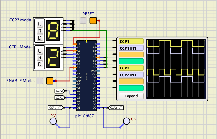
For example this could be a circuit to test Compare and PWM modes of a CCP module:
And this the code:
If you are up to the challenge, please let me know and we will start to work immediately.
This is an HUGE task and writing the code is just a part of it.
Testing every feature of every Microcontroller is an overwhelming task.
For this, we need your help.
Reporting bugs if you find some is very important, but we need methodic testing of every periferical and feature of each model.
If you are interested in getting some specific Microcontroller working, you can collaborate testing it.
We will work closely in a fast iteration manner to ensure that all issues are solved immediately.
Microcontrollers with testers working in it have total preference.
This means that I will work first with testers and then in anything else.
What should a tester do?
- First get a defined task, if you don't have some specific interest, there are tasks waiting to be done.
For example one task could be: testing certain variant of PIC CCP module.
- Create Circuits and code to perform the testing.
Preferably one circuit+program can be used to test several configurations.
Some times, several circuits and/or programs would be needed.
- Now the test cycle starts:
1: Test and report what is working or not.
2: Errors will be fixed and new simulide builds shared.
3: Goto 1
Ussually this should be done in several steps. First testing the basic and most used features, later the more fancy stuff.
These test units should be simple and easy to use.
Don't use other perifericals, only Ports.
Don't use libraries, only low level code.
Designing a simple circuit and program that can perform good testing is a real challenge, so you will need to use all your imagination and knowledge.
For example this could be a circuit to test Compare and PWM modes of a CCP module:

And this the code:
- Code:
// Compiler: Mplabx_xc8  Device: 16f887

#define _XTAL_FREQ 20000000UL       // crysTAL FREQuency

#include <xc.h>
#include <pic16f887.h>

#include "ccp00.h"    // CCP Modes

void __interrupt() myisr() // Interrupsion SubRoutine (ISR)
{
    if( CCP1IF ){        // CCP1 Interrupt
        PORTD ^= 0b00000010;
        CCP1IF = 0;
    }
    if( CCP2IF ){        // CCP2 Interrupt
        PORTD ^= 0b00000100;
        CCP2IF = 0;
    }
}

void main()
{
    ANSEL = 0;
    ANSELH = 0;

    TRISD = 0;
    TRISC = 0;
                          // Configure Timer1 To Operate In Timer Mode
    TMR1 = 0;             // Clear Timer1 Register. To start counting from 0
    TMR1CS = 0;           // Set clock source (timer mode)
    T1CKPS0 = 0;          // Set prescaler ratio (1:1)
    T1CKPS1 = 0;
    TMR1ON = 1;           // Start Timer 1

    CCP1CON = comTog;     // CCP1 Compare mode, toggle on match
    CCPR1H = 128;         // Match at 32768, 50% duty
    CCP1IE = 1;           // Enable CCP1 Interrupt

    CCP2CON = comSET;     // CCP2 Compare mode, set output on match
    CCPR2H = 128;         // Match at 32768, 50% duty
    CCP2IE = 1;           // Enable CCP2 Interrupt

    PEIE = 1;             // Enable Periferical Interrupts
    GIE = 1;              // Enable General Interrupts

    __delay_ms( 500 );

    while (1)
    {
        if( RE0 == 1 ){
            CCP1CON = PORTA;
            CCP2CON = PORTB;
        }
        __delay_ms( 100 );
    }
}
- Code:
// CCP1 and CCP2

#define ccpOFF 0b00000000 // Capture/Compare/PWM off (resets ECCP module)
#define capFal 0b00000100 // Capture mode, every falling edge
#define capRis 0b00000101 // Capture mode, every rising edge
#define cap04R 0b00000110 // Capture mode, every 4th rising edge
#define cap16R 0b00000111 // Capture mode, every 16th rising edge
#define comSET 0b00001000 // Compare mode, set output on match (CCP1IF bit is set)
#define comCLR 0b00001001 // Compare mode, clear output on match (CCP1IF bit is set)
#define comInt 0b00001010 // Compare mode, generate software interrupt on match (CCP1IF bit is set, CCP1 pin is unaffected)
#define comSpe 0b00001011 // Compare mode, trigger special event (CCP1IF bit is set; CCP1 resets TMR1 or TMR2

// CCP1 = enhanced:
#define comTog 0b00000010 // Compare mode, toggle output on match (CCP1IF bit is set)
#define pwm1_0 0b00001100 // PWM mode; P1A,C active-high; P1B,D active-high
#define pwm1_1 0b00001101 // PWM mode; P1A,C active-high; P1B,D active-low
#define pwm1_2 0b00001110 // PWM mode; P1A,C active-low;  P1B,D active-high
#define pwm1_3 0b00001111 // PWM mode; P1A,C active-low;  P1B,D active-low

// CCP2:
#define pwm2_0 0b00001100 // PWM mode;
If you are up to the challenge, please let me know and we will start to work immediately.
Last edited by arcachofo on Thu Jan 06, 2022 1:39 pm; edited 3 times in total (Reason for editing : Add information.)


