Would you like to react to this message? Create an account in a few clicks or log in to continue.

You are not connected. Please login or register

Equivalent to CD4046 Phase Locked Loop

3 posters

Go down  Message [Page 1 of 1]

1Equivalent to CD4046 Phase Locked Loop Empty Equivalent to CD4046 Phase Locked Loop Wed Nov 23, 2022 7:25 pm

KerimF

KerimF

I wonder if it is possible adding a component which could be somehow equivalent to CD4046 (used to build a phase locked loop circuit).

Its simplest version could consist of a linear voltage-controlled oscillator (VCO) and a digital comparator (XOR gate).

Pins:
Signal input
Comparator input
Comparator output
VCO input
VCO output
(VDD and GND)

The two parameters that could replace the external C1, R1 and R2 are:
The VCO maximum frequency (Fmax) , when VCOin=VDD
The VCO minimum frequency (Fmin) , when VCOin=0

Note:
The VCO center frequency, Fo = (Fmax + Fmin)/2 , when VCOin=VDD/2
The lock frequency range = Fmax - Fmin

Alex68 likes this post

2Equivalent to CD4046 Phase Locked Loop Empty Re: Equivalent to CD4046 Phase Locked Loop Wed Nov 23, 2022 11:24 pm

arcachofo

arcachofo

I wonder if it is possible adding a component which could be somehow equivalent to CD4046 (used to build a phase locked loop circuit).
You can do it with an "Scripted" Component:
https://simulide.forumotion.com/t990-custom-components

This can only be done in development branch (trunk).
There are 2 examples (used in the video).
You can have a look at: data/scripted/DAC to see the files.

Alex68 likes this post

KerimF

KerimF

It seems it is not trivial, or it is simply proposed as homework Smile , to make a VCO block in SimulIDE having two terminals:

An input for an analog signal (Vin) that can vary between Vdd and ground.

An output that produces a squarewave (50% duty cycle) whose frequency equals to (Fmax-Fmin)*Vin/Vdd.

Where Fmax, Fmin and Vdd are user's parameters.

Alex68

Alex68

I also wanted to have this model!

KerimF likes this post

Alex68

Alex68

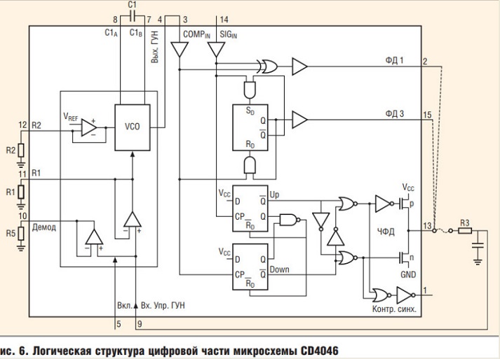
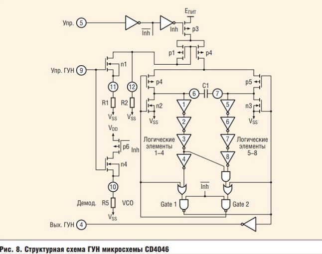
Equivalent to CD4046 Phase Locked Loop 2022-587
Equivalent to CD4046 Phase Locked Loop 2022-588
Equivalent to CD4046 Phase Locked Loop 2022-589

Alex68

Alex68

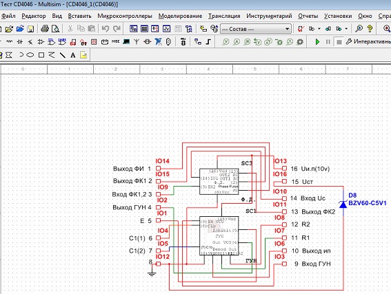
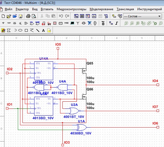
Equivalent to CD4046 Phase Locked Loop 2022-590
Equivalent to CD4046 Phase Locked Loop 2022-591
Equivalent to CD4046 Phase Locked Loop 2022-592

Alex68

Alex68

NOT SO EASY TO MAKE THIS MODEL

KerimF

KerimF

I also can simulate CD4046 (or its new equivalent ICs) using LTspiceIV (which I was allowed to download before 'Linear Technology' and its personnel was bought by 'Analog Devices').

So, lately, I was able simulating my 1-PLL demodulator for AM double sideband suppressed carrier. I first built it (as MS thesis) in 1979. Actually, it demodulates any AM signal, m=0 (carrier only) to m= infinity (carrier suppressed). Being simple and reliable, I used it, for many years, in my private short-range RF voice links between home and workplace in the 80's (when I had no phone line at home since I was living, at that time, in a rather poor neighborhood). I used it as a simple scrambling method so that the transmitted voice cannot be heard by any radio sets (on AM band it sounds as noise and on FM band it gives no sound at all).

Now, I am surprised that, even after more than 40 years, the topology of my demodulator is claimed non-existing in all universities around the world!
One of its advantages is that it could be integrated in a simple low-cost IC.
For instance, the known DSB-SC demodulators are of Costas Loop (it uses 2-PLL in quadrature, not easy to implement) and of the squaring method (that needs a selective band-pass filter, so the carrier frequency should be fixed)

A few years ago, I posted my work, as a gift, in a forum related to Analog Devices. Soon after, I got an email to apologize and inform me that they have no right to talk to me and they are forced to ban me from their forum!

Alex68 likes this post

KerimF

KerimF

Alex68 wrote:NOT SO EASY TO MAKE THIS MODEL

I was thinking of just an ideal (mathematical) model with one input and one output Laughing

10Equivalent to CD4046 Phase Locked Loop Empty Re: Equivalent to CD4046 Phase Locked Loop Thu Nov 24, 2022 9:41 am

Alex68

Alex68

Добрый День KerimF !!! (пишу на русском, боюсь если переведет мой переводчик то многое не понятно будет)

Я использую эту модель но в программе Multisim 14.2 Она сделана у меня там. Работает хорошо.
В основном мы применяли микросхему в разработках и называлась она 564ГГ1. Аналог CD4046. В основном делали на ней различные умножители частоты на различных частотных синтезаторах.
В нашей программе я пока ее модель не пробовал делать. Сложность будет заключаться при построении генератора управляемым напряжением.
Попробуйте, может получиться. Удачи !!!

11Equivalent to CD4046 Phase Locked Loop Empty Re: Equivalent to CD4046 Phase Locked Loop Thu Nov 24, 2022 1:35 pm

KerimF

KerimF

Alex68 wrote:Good Afternoon KerimF !!! (I am writing in Russian, I am afraid if my translator translates then much will not be clear)

I use this model but in the program Multisim 14.2 It is made by me there. Works well.
Basically, we used the chip in development and it was called 564GG1. Analogue of CD4046. Basically, they made various frequency multipliers on it on various frequency synthesizers.
In our program, I have not yet tried to make its model. The difficulty will lie in the construction of a generator with a controlled voltage.
Try it, it may work. Good luck!!!

From your works here, it seems to me that you are good, if not professional, in modelling devices and verifying, when necessary, some already-made models, as well.

On my side, I have to focus, almost monthly (if not weekly sometimes), on how to update the design (with the necessary hardware/firmware tests) of my various controllers/products to keep them competitive among similar ones which are imported from abroad (China for example) or made locally. And I have to succeed continuously (in order to keep gaining our daily bread) while using old tools and components at work.

I heard of NE564 (its typical 'fo' is around 60 MHz) but I couldn't get it.
Fortunately, the AM intermediate frequency (IF) is just 455 KHz, and in my demodulator the VCO center frequency needs to be set at 2*IF (910 KHz) which is not high for CD4046 (if Vdd = 10V or higher). And, in the case of FM band, the frequency of my suppressed sub-carrier was just 32768 Hz (of a crystal) that replaced the 38 KHz (which is modulated by L - R audio signal in stereo FM) and its pilot 19 KHz (my demodulator doesn't need a pilot since it can recover the suppressed carrier, frequency and phase, from the two side bands only).

Sorry to give you the impression that I may work in modeling the proposed ideal (parametrical) VCO when I said: "I was thinking of". I had to say instead "I meant'  Embarassed

By curiosity, may I ask why modeling such a very simple well-defined ideal block (not built by passive and active components as in a real device) could be hard to do by the professional members in this field here?

12Equivalent to CD4046 Phase Locked Loop Empty Re: Equivalent to CD4046 Phase Locked Loop Thu Nov 24, 2022 2:12 pm

Alex68

Alex68

KerimF, мне наша программа помогает перед тем как сделать устройство в печати, промоделировать схему. В основном на цифровых микросхемах и некоторых типах контроллерах.
Это мне нужно для работы в основном. Мне в ней все хватает из элементной базы. Правда пока нет моделей разных оптронов, трансформаторов.
Коммерцией я не занимаюсь. Работаю еще пока. Ребята просят что бы я их не бросал. Да и вообще без работы не могу. А так у меня хорошая пенсия и плюс заработок на работе.
Вы бы скинули какой нибудь интересный свой проект ?
Насчет модели CD4046 я верю что вы сделаете его. Тогда скиньте посмотреть !
Спасибо.

13Equivalent to CD4046 Phase Locked Loop Empty Re: Equivalent to CD4046 Phase Locked Loop Thu Nov 24, 2022 5:52 pm

KerimF

KerimF

Alex68 wrote: KerimF, our program helps me to model the scheme before making the device in print. Mainly on digital chips and some types of controllers.
That's what I need for work basically. I have enough of everything in it from the element base. True, there are no models of different optocouplers, transformers yet.
I don't do business. I'm still working. The guys are asking that I don't leave them. And I can't do it without a job. And so I have a good pension and plus earnings at work.
Would you throw off any interesting project?
As for the CD4046 model I believe you will make it. Then throw in a look!
Thank you.

Hi Alex,

My first step in every design is to know, as much as possible, the characteristics of every component I can use (available in quantity and at a reasonable price). So, almost all my readings are of the form of datasheets Smile
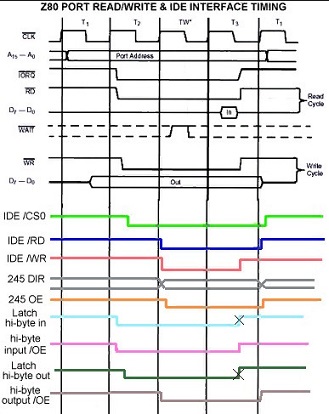
My first machine code, I wrote it in 1980, was for Z80 CPU. I wrote it on paper, bit by bit (an instruction my take 8, 16 or 24 bits). Then, to test it, I had to enter it also bit by bit manually into a set of dynamic memory (RAM of a programmer I made) before transferring it all into an EPROM (which could be erased by ultraviolet). So, even without having an assembler (to translate English to machine code), it was possible for me to do it because I was able having first a very detailed datasheet of Z80. This code was relatively very small. It just displays, on an outdoor panel, a text written/programmed also in the EPROM. But it took me two months to debug it fully (because if one bit was wrong, the entire code had to be rewritten!). Now, it may take 2 hours at most.

In case of a simulator, as SimulIDE or else, if I see a real necessary to make a block model for it, I will have no choice but to study in depth first how the simulator engine accepts and understands the various words (names, labels, numbers, symbols, delimiters... etc.) that can define a model. And since I couldn't be familiar (due to the world's regulations) with the languages (and the global objects, functions, structures... etc.) of the new C/C++ or Qt compiler, this study becomes even harder for me. This explains while I simply focused on writing codes in assembly (usually complex) for some MCUs, after I was able having their full datasheet, assembler and programmer.

I wish I can help more than pointing out a discovered bug. I don't have any of the advanced facilities that almost all engineers around the world can get, for free or not.

Kerim

Alex68 likes this post

14Equivalent to CD4046 Phase Locked Loop Empty Re: Equivalent to CD4046 Phase Locked Loop Fri Nov 25, 2022 6:04 am

Alex68

Alex68

Добрый День, KerimF !

Можете вспомнить молодость, Z80 есть в сборке R1408. Я просто включил его на перебор адресов. Я то же в 85 году изучал его структуру. Это были наши первые процессоры. Даже кое что делали на них. Но к нему надо много еще различных навесок. У меня даже полностью есть весь набор этих девайсов. Ток они потребляли большой. Платы были очень большие.
Можете потестировать его во всех режимах.Equivalent to CD4046 Phase Locked Loop 2022-596

Equivalent to CD4046 Phase Locked Loop 2022-597Equivalent to CD4046 Phase Locked Loop 2022-598

KerimF likes this post

15Equivalent to CD4046 Phase Locked Loop Empty Re: Equivalent to CD4046 Phase Locked Loop Sun Nov 27, 2022 4:54 pm

arcachofo

arcachofo

KerimF wrote:By curiosity, may I ask why modeling such a very simple well-defined ideal block (not built by passive and active components as in a real device) could be hard to do by the professional members in this field here?
There is no plan to add this component.
You can do it yourself easily, you only need to learn a few basic things and then you can create many basic analog blocks.

First you need the development version of simulide:
https://simulide.forumotion.com/t550-simulide-trunk-tester-builds

If you have a look at these folders you will see 2 components  defined by 3 very simple files:
data/scripted/DAC
data/scripted/signal

You need to create a folder data/scripted/VCO and add your version of those files.
You can just copy/paste some of the existing files and edit them, I would use:
data/scripted/DAC/dac.mcu
data/scripted/DAC/dac_core.as
data/scripted/signal/signal_LS.package

Copy those files and paste in the folder you created: data/scripted/VCO
Then rename to vco.mcu, vco_core.as and vco_LS.package

Now edit those files to meet your requirements.
vco.mcu:
Edit to this:
Code:
<!DOCTYPE SimulIDE>

<iou name="VCO" core="scripted" script="vco_core.as" >
    
    <ioport name="PORTA" pins="In,Out" />
    
</iou>

vco_core.as:
Edit to this (by now):
Code:

// PinModes: undef_mode=0, input, openCo, output, source

IoPin@  inputPin  = component.getPin("In");
IoPin@  outputPin = component.getPin("Out");

void setup()
{
    print("VCO init ");
}

void reset()
{
    print("resetting VCO");
    
    inputPin.setPinMode( 1 ); // Input
    outputPin.setPinMode( 3 );  // Output
    outputPin.setVoltage( 0 );
    
    InputPin.changeCallBack( element, true ); // Register for Input Pin voltage changes
}

void voltChanged()
{
    double input = inputPin.getVoltage();
    print("DAC input changed " + input );
    
    outputPin.setVoltage( input );
}

The package file should be edited graphically, see "Creating Package Files:" here:
https://www.simulide.com/p/new-subcircuits.html
But it is very easy to edit manually.
vco_LS.package:
Edit to this:
Code:
<!DOCTYPE SimulIDE>

<!-- This file was generated by SimulIDE -->

<packageB name="Package" width="4" height="4" background="" type="None" >

    <pin type=""    xpos="-8"   ypos="16"   angle="180" length="8"  id="In"   label="In"  />
    <pin type=""    xpos="40"   ypos="16"   angle="0"   length="8"  id="Out"  label="Out" />
    
</packageB>

Now open data/scripted.xml and add an entry for you new component:
Code:
<!DOCTYPE SimulIDE>

<itemlib>
    
    <itemset category="Scripted" type="MCU" >
        
        <item name="VCO" package="scripted/VCO/vco" data="scripted/VCO/vco"></item>
        <item name="DAC" package="scripted/DAC/dac" data="scripted/DAC/dac"></item>
        <item name="Signal" package="scripted/signal/signal" data="scripted/signal/signal"></item>
    
    </itemset>
    
</itemlib>

Your component should appear in the component list (at the end) next time you open simulide.

By now the only thing it does is: Output voltage = input voltage.

Next thing will be to add a clock generator and link it to input voltage.

KerimF likes this post

16Equivalent to CD4046 Phase Locked Loop Empty Re: Equivalent to CD4046 Phase Locked Loop Sun Nov 27, 2022 6:22 pm

KerimF

KerimF

arcachofo wrote:
By now the only thing it does is: Output voltage = input voltage.

Next thing will be to add a clock generator and link it to input voltage.

Wow, so you know how to do it Shocked  Smile
If you don't, do you really think I am better than you in doing it  Wink

Anyway, I will try following your steps and see to what they will lead me.
Thank you.

17Equivalent to CD4046 Phase Locked Loop Empty Re: Equivalent to CD4046 Phase Locked Loop Sun Nov 27, 2022 8:07 pm

arcachofo

arcachofo

Wow, so you know how to do it
If you don't, do you really think I am better than you in doing it
Yes, I know how to do it, but this component is not to be added to simulide, so I don't want to do it.
It's you who want this component, so I can help you to learn how to do and then you can do this and many other analog blocks you might need.

18Equivalent to CD4046 Phase Locked Loop Empty Re: Equivalent to CD4046 Phase Locked Loop Mon Nov 28, 2022 1:59 pm

KerimF

KerimF

arcachofo wrote:
Wow, so you know how to do it
If you don't, do you really think I am better than you in doing it
Yes, I know how to do it, but this component is not to be added to simulide, so I don't want to do it.
It's you who want this component, so I can help you to learn how to do and then you can do this and many other analog blocks you might need.

Sorry, I was just kidding. You were very clear that such a component is not supposed to be added to SimulIDE's list.

19Equivalent to CD4046 Phase Locked Loop Empty Re: Equivalent to CD4046 Phase Locked Loop Mon Nov 28, 2022 6:08 pm

arcachofo

arcachofo

@KerimF:
Creating these components is relatively easy.
I will do a tutorial when this feature is more completed, but here are some basic explanations:

There are 3 files:
name.mcu:
This file describes the device: type, internal components and some other characteristics.

For this VCO it is very simple, just an Input Pin and an Output Pin.
Pins are always included in Ports, even if it is a single Pin.

If you have a look at vco.mcu you will se that it just describes the type, the script used and a Port with 2 pins:
Code:

<iou name="VCO" core="scripted" script="vco_core.as" >
    
    <ioport name="PORTA" pins="In,Out" />
    
</iou>

A Microcontroller for example will have other stuff inside like RAM, ROM, Timers, Usart, ADC, etc.


name.package:
This file describes the external package, what you see in the circuit.
Pin Ids must be the same used in name.mcu.

This file is not supposed to be edited manually, but graphically using "package" component:
https://www.simulide.com/p/new-subcircuits.html


name.as:
This is the script that describes the behavior of the device.
There are some functions and procedures that must be used to interface with simulide.
Syntax is similar to C++, but even if you don't know C++ you can understand it perfectly and just use the same syntax.

I will explain what is used in this VCO:

1- You need to get "handlers" for the Pins you are using:
Code:
IoPin@  inputPin  = component.getPin("In");
IoPin@  outputPin = component.getPin("Out");
Now "inputPin" and "outputPin" are the handlers for your Pins.
Note that we request Pin handlers using the same names defined in .mcu file.

2- Functions:
SimulIDE will always call some functions (if they are defined in the script):

setup() Called when the component is created (only prints a message in VCO).
reset() Called every time the simulation starts. Used to initialize stuff.

In this VCO component it sets one pin to be an input and other to output:
Code:
    inputPin.setPinMode( 1 ); // Input
    outputPin.setPinMode( 3 );  // Output
Note that we are using the handlers created previously.

Then we initialize the voltage for the output Pin:
Code:
    outputPin.setVoltage( 0 );

We want to Know when the input Pins changes voltage to recalculate our output.
For that we use changeCallBack() :
Code:
    inputPin.changeCallBack( element, true ); // Register for Input Pin voltage changes
"element" is just a pre-made handler, it just must be like this.
"true/false" if you want to register or unregister for voltage changes.

Now, every time Input Pin changes voltage SimulIDE will call the function voltChanged()

So in voltChanged() we read the voltage of Input Pin and do whatever we want:
Code:
void voltChanged()
{
    double input = inputPin.getVoltage();
    print("DAC input changed " + input );
    
    outputPin.setVoltage( input );
}
Note that in this case it just sets output voltage = input voltage.
But you can do some calculations here and set the output voltage or whatever you want.

Note that you can use the print() function to print messages in the bottom panel.

For the VCO component we don't want to set the output voltage here but generate a clock signal.
This requires an extra step and the use of another function, but I think it is better to go step by step and be sure you get this working and understand the basics.


To create other "analog blocks" you can just copy/paste these files and edit them with your requirements.

20Equivalent to CD4046 Phase Locked Loop Empty Re: Equivalent to CD4046 Phase Locked Loop Mon Nov 28, 2022 11:14 pm

KerimF

KerimF

arcachofo wrote:@KerimF:
...but I think it is better to go step by step and be sure you get this working and understand the basics.
To create other "analog blocks" you can just copy/paste these files and edit them with your requirements.

It is a good start, and your clear explanation is encouraging.
Thank you for your time.

21Equivalent to CD4046 Phase Locked Loop Empty Re: Equivalent to CD4046 Phase Locked Loop Wed Nov 30, 2022 10:55 am

KerimF

KerimF

I did the first step and got:

Initializing VCO-1
VCO-1 Initialized: 0 MHz

script line: 12 1 INFO Compiling void reset()
script line: 20 5 ERROR No matching symbol 'InputPin'
ScriptModule::compileScript: Build() failed
Warning: MainWindow::getHelp: File not found
D:/SimulIDE/SimulIDE-R1408_Win32_sub/data/help/vco.txt

Added_1:
It seems, the actual syntax is case sensitive.

Added_2:
fixed
Attachments
Equivalent to CD4046 Phase Locked Loop AttachmentVCO_01.zip
You don't have permission to download attachments.
(2 Kb) Downloaded 4 times

22Equivalent to CD4046 Phase Locked Loop Empty Re: Equivalent to CD4046 Phase Locked Loop Wed Nov 30, 2022 6:37 pm

arcachofo

arcachofo

Nice you could fix the syntax error.
Yes syntax is case sensitive.

Now we have a working component that reads the input and sets the output voltage = input voltage.
But we want to generate a clock signal.

To do this we need to use "events" in the simulator usin the functions:
addEvent( time );
This function tells the simulator to call us at a certain time in the future (in picoseconds).

cancelEvents();
This function will cancel events previously scheduled but not executed.

runEvent();
This is the function the simulator will call when time is reached.
We need to implement this function in our script.


So first we need to calculate that time from the input voltage.
Note we need the time of half period because we will toggle output Pin.

Then we cancel previous events and schedule a new event with the new time.

And in the function runEvent() we toggle the output Pin and schedule a new event to keep it running.


I don't know how it should work:
Does it just convert voltage to frequency or there is a central freq and it swings around?

I did a simple conversion from volts to kHz, this is the code for the script:
Code:
// PinModes: undef_mode=0, input, openCo, output, source

IoPin@  inputPin  = component.getPin("In");
IoPin@  outputPin = component.getPin("Out");

bool outState;
uint64 time;

void setup()
{
    print("VCO init ");
}

void reset()
{
    print("resetting VCO");
    
    outState = false;
    
    inputPin.setPinMode( 1 );   // Input
    outputPin.setPinMode( 3 );  // Output
    outputPin.setVoltage( 0 );
    
    inputPin.changeCallBack( element, true ); // Register for Input Pin voltage changes
}

void voltChanged()
{
    double input = inputPin.getVoltage();

    time = 1e9/input/2;                      // Volts to kHz ( Do your calculations instead )
    
    print("Input Voltage " + input + " 1/2 Period ps = " + time );
    
    component.cancelEvents();
    if( time > 0 ) component.addEvent( time );
}

void runEvent()
{
    if( outState ) outputPin.setVoltage( 5 );
    else           outputPin.setVoltage( 0 );
    
    outState = !outState; // Invert State
    
    component.addEvent( time );
}

Note that I created 2 global variables:
outState: boolean to keep track of output Pin State.
time: Unsigned integer 64 bits to keep track of time for 1/2 period.

And added the function runEvent() to toggle the output Pin.

With this and some tweaking you can do what you want.

Some tips:
You can open the script in simulide, modify and test in a circuit.
But for the component to get the new script you need to reload the circuit (I need to add something to solve this).

Any problem or doubt about C++ syntax let me know.

Sponsored content


Back to top  Message [Page 1 of 1]

Permissions in this forum:
You cannot reply to topics in this forum