 Latest images
Timer issue solved at Rev 1069.

![]() Message [Page 2 of 3]
Message [Page 2 of 3]
26 Re: 8051 - The CNJE instruction with Registers make the simulation stop Sun Apr 10, 2022 5:18 pm
arcachofo

27 Re: 8051 - The CNJE instruction with Registers make the simulation stop Mon Apr 11, 2022 10:30 pm
arcachofo
Uart working at Rev 1071.
28 Re: 8051 - The CNJE instruction with Registers make the simulation stop Thu Jan 12, 2023 1:31 pm
diego_souza
Hi,
I'm testing the 8051 with 1.0.0-RC3 and here are some new findings.
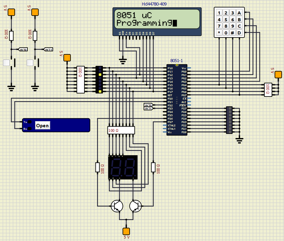
Please find the SimulIDE circuit and ASM+HEX at the following shared folder: https://drive.google.com/drive/folders/1HCtEGP7ASYCHW9SiBTbSsD_ODLuhGCGE?usp=sharing
- The RESET is working with the wrong logic. The way it is now, you need to keep HIGH for it to work (or not connect RST at all). However, the correct is - if you set RST as HIGH for two cycles, and return it to LOW, it will reset the program.
- In previous releases, having a capacitor on the circuit really affected the timing. Now, it seems to be 99% better, however, I noticed it still affects the timing (you may clearly see this with the multiplexed 7 segment display example in the shared folder).
- The "Open Serial Monitor -> USart1" option only works if a "SerialPort" peripheral is added to the circuit. If not, the simulation freezes. With the peripheral connected, the UART examples works, except for example 4.
- The UART example for (send a value to 8051 so it is reflected in the PORT) freezes the simulation.
- When simulating the interrupt example programs (50 ms change on P1.0 on program 12 and 1 ms change on P1.0 on program 13), when connecting an oscope it seems the interval is (a liiiitle bit) higher than that. I'm not sure if this is related to the 8051 timing precision or if is something related to the simulation.
- The Asem-51 compilation is not working. For it to work, you need to change: \data\codeeditor\compilers\assemblers\asem51.xml to command="ASEM.exe". With that, the compilation works, HOWEVER, when you make a change (e.g. change the number of delays calls in the delay program, compile it and upload it, the change is not reflected in the circuit. Note: The terminal says the compilation was OK.
Regarding the implementation of external memory, do you have a simulation done with other MCUs so I can take a look before trying? Just want to see the used components, etc... (I remember seeing an example on the forum, but I can't remember exactly where).
I'm testing the 8051 with 1.0.0-RC3 and here are some new findings.
Please find the SimulIDE circuit and ASM+HEX at the following shared folder: https://drive.google.com/drive/folders/1HCtEGP7ASYCHW9SiBTbSsD_ODLuhGCGE?usp=sharing
- The RESET is working with the wrong logic. The way it is now, you need to keep HIGH for it to work (or not connect RST at all). However, the correct is - if you set RST as HIGH for two cycles, and return it to LOW, it will reset the program.
- In previous releases, having a capacitor on the circuit really affected the timing. Now, it seems to be 99% better, however, I noticed it still affects the timing (you may clearly see this with the multiplexed 7 segment display example in the shared folder).
- The "Open Serial Monitor -> USart1" option only works if a "SerialPort" peripheral is added to the circuit. If not, the simulation freezes. With the peripheral connected, the UART examples works, except for example 4.
- The UART example for (send a value to 8051 so it is reflected in the PORT) freezes the simulation.
- When simulating the interrupt example programs (50 ms change on P1.0 on program 12 and 1 ms change on P1.0 on program 13), when connecting an oscope it seems the interval is (a liiiitle bit) higher than that. I'm not sure if this is related to the 8051 timing precision or if is something related to the simulation.
- The Asem-51 compilation is not working. For it to work, you need to change: \data\codeeditor\compilers\assemblers\asem51.xml to command="ASEM.exe". With that, the compilation works, HOWEVER, when you make a change (e.g. change the number of delays calls in the delay program, compile it and upload it, the change is not reflected in the circuit. Note: The terminal says the compilation was OK.
Regarding the implementation of external memory, do you have a simulation done with other MCUs so I can take a look before trying? Just want to see the used components, etc... (I remember seeing an example on the forum, but I can't remember exactly where).
29 Re: 8051 - The CNJE instruction with Registers make the simulation stop Thu Jan 12, 2023 4:24 pm
arcachofo
Hi Diego and thanks for the circuit and code, it will be very useful for testing.
I'm not sure how to solve this. Right now it is hardcoded for all Micros that reset is active low. But I will find a solution.
This has been optimized quite a bit, but a capacitor can add a lot of cpu usage, specially if combinen with non linear components.
You can reduce the cpu usage by increasing the Reactive step in Simulation settings, but specially by not using capacitors if not really needed.
What I see is problems with Usart if pins P3.0 and P3.1 are not connected (does not need to be a Serial Port).
It also freezes with pgm_17_uart_ex4.
So definitely some problems going on with Uart.
Not sure how this timing is determined, it could be wrong number of cycles in some instructions, but will probably show up in blinking leds as well.
Let me have a look at the asm code...
In general the compiler commands should be modified to match your system, not only executable names, but also path or whatever.
You should see this message at the bottom panel:
Seems that I didn't publish this code, it is still in a local repository I did to implement it.
In any case I'm now focusing in finishing version 1.0.0, so let's fix the issues you reported then we go into the external memory, which is in fact a new implementation of 8051 core (but peripherals are the same).
Ok, I didn't know that Reset works the opososite.- The RESET is working with the wrong logic. The way it is now, you need to keep HIGH for it to work (or not connect RST at all). However, the correct is - if you set RST as HIGH for two cycles, and return it to LOW, it will reset the program.
I'm not sure how to solve this. Right now it is hardcoded for all Micros that reset is active low. But I will find a solution.
Yes, capacitors can slow down the simulation.- In previous releases, having a capacitor on the circuit really affected the timing. Now, it seems to be 99% better, however, I noticed it still affects the timing (you may clearly see this with the multiplexed 7 segment display example in the shared folder).
This has been optimized quite a bit, but a capacitor can add a lot of cpu usage, specially if combinen with non linear components.
You can reduce the cpu usage by increasing the Reactive step in Simulation settings, but specially by not using capacitors if not really needed.
For me the Serial Monitor looks ok.- The "Open Serial Monitor -> USart1" option only works if a "SerialPort" peripheral is added to the circuit. If not, the simulation freezes. With the peripheral connected, the UART examples works, except for example 4.
What I see is problems with Usart if pins P3.0 and P3.1 are not connected (does not need to be a Serial Port).
It also freezes with pgm_17_uart_ex4.
So definitely some problems going on with Uart.
Yes, I see.- When simulating the interrupt example programs (50 ms change on P1.0 on program 12 and 1 ms change on P1.0 on program 13), when connecting an oscope it seems the interval is (a liiiitle bit) higher than that. I'm not sure if this is related to the 8051 timing precision or if is something related to the simulation.
Not sure how this timing is determined, it could be wrong number of cycles in some instructions, but will probably show up in blinking leds as well.
Let me have a look at the asm code...
Yes, in Windows is like that.- The Asem-51 compilation is not working. For it to work, you need to change: \data\codeeditor\compilers\assemblers\asem51.xml to command="ASEM.exe". With that, the compilation works,
In general the compiler commands should be modified to match your system, not only executable names, but also path or whatever.
It is working for me...HOWEVER, when you make a change (e.g. change the number of delays calls in the delay program, compile it and upload it, the change is not reflected in the circuit. Note: The terminal says the compilation was OK.
You should see this message at the bottom panel:
- Code:
FirmWare Uploaded to 8051
/media/user/soft/simulide/tests/MCU/mcs-51/8051-Diego/ASM and HEX files/pgm_02_delay.hex


Mapping Flash to Source... x lines mapped
Let me update the code for this.Regarding the implementation of external memory, do you have a simulation done with other MCUs so I can take a look before trying? Just want to see the used components, etc... (I remember seeing an example on the forum, but I can't remember exactly where).
Seems that I didn't publish this code, it is still in a local repository I did to implement it.
In any case I'm now focusing in finishing version 1.0.0, so let's fix the issues you reported then we go into the external memory, which is in fact a new implementation of 8051 core (but peripherals are the same).
30 Re: 8051 - The CNJE instruction with Registers make the simulation stop Fri Jan 13, 2023 11:16 am
arcachofo
Reset and Uart issues solved.
There are new builds available for testing:
https://simulide.forumotion.com/t390-simulide-1-0-0-tester-builds
There are new builds available for testing:
https://simulide.forumotion.com/t390-simulide-1-0-0-tester-builds
31 Re: 8051 - The CNJE instruction with Registers make the simulation stop Sun Jan 15, 2023 2:31 am
diego_souza
Thanks for the update!
The reset circuit is working well now!
And all 4 UART examples are also working, including example n°4 (send a value to the UART [e.g. "1"] and pass this value to P1).
The only detail is that P3.0 and P3.1 need to be connected to something (not necessarily a serial port - actually tested connecting both to GND).
I wonder if it needed to work without any connection...
Another nice detail: the simulation doesn't freeze when there's no COM port to be connected and you OPEN it.
Now a random question not related o 8051: Will v1.0.0 have all the MCUs like v0.4.15? I'm missing some of the MCU available, like the PIC16F877A.
Thanks!
Diego
32 Re: 8051 - The CNJE instruction with Registers make the simulation stop Sun Jan 15, 2023 2:42 am
diego_souza
Hi,
One more comment:
- For some reason, the timing definitively has a problem.
The example 11 (1 second blink using timer), is producing a 1.1 blink.
Thanks,
Diego
One more comment:
- For some reason, the timing definitively has a problem.
The example 11 (1 second blink using timer), is producing a 1.1 blink.
Thanks,
Diego
33 Re: 8051 - The CNJE instruction with Registers make the simulation stop Sun Jan 15, 2023 12:58 pm
arcachofo
It is working for me,The only detail is that P3.0 and P3.1 need to be connected to something (not necessarily a serial port - actually tested connecting both to GND).
What problem do you experience?
Fast reply: no.Now a random question not related o 8051: Will v1.0.0 have all the MCUs like v0.4.15?
1.0.0 uses a new MCU simulator, so all devices must be implemented from scratch.
And I will not implement devices without help, for example as you are doing with 8051.
Some devices are in the list but not finished, when someone comes and help with it then it will be finished.
Help meaning at least testing and reporting problems and then testing the solutions.
Specially PICs are in very bad shape: almost nobody is testing and reporting problems.
In addition Implementing PICs is a nightmare:
- Peripheral design is full of non-sense (mostly to save a few registers).
- Lot of variation of the same peripherals in different devices.
- Datasheets are literally crap: explanations are a mess, and full of errors and contradictions.
There is PIC16F877 that should work almost the same.I'm missing some of the MCU available, like the PIC16F877A.
If there is some difference that causes problems I can implement it.
34 Re: 8051 - The CNJE instruction with Registers make the simulation stop Sun Jan 15, 2023 9:14 pm
diego_souza
Hi,
It is working for me, What problem do you experience?
The UART is working fine (for all 4 examples), but pins P3.0 and P3.1 need to be connected to something (I thought they would work like the Arduino board, which work well even if the TX and RX pins are not connected). In the other hand, I don't see any problems connecting P3.0 and P3.1 to a SerialPort component.
So, the only detail I'm seeing that is pending now is the timing issue (program 11 generating a 1.1 s delay instead of 1 s.).
Regarding the MCUs in v1.0.0, I totally understand!
There is PIC16F877 that should work almost the same.
Yes, very similar indeed. Just using PIC16F877A in the simulations because I have one here.
Thanks!
35 Re: 8051 - The CNJE instruction with Registers make the simulation stop Sun Jan 15, 2023 9:58 pm
arcachofo
I don't understand what you exactly mean by "not working".The UART is working fine (for all 4 examples), but pins P3.0 and P3.1 need to be connected to something (I thought they would work like the Arduino board, which work well even if the TX and RX pins are not connected). In the other hand, I don't see any problems connecting P3.0 and P3.1 to a SerialPort component.
There is an optimization to save some cpu: if Uart pins are not connected, then all the bit banging routine is skipped.
But Serial Monitor still works, so you can see what the MCU is sending or send data to the MCU from the Monitor.
So Uart should work in both cases, but if nothing connected then nothing goes to the pins.
Or at least that is how it should work.
In Arduinos the internal MCU is connected to the Arduino Board pins, so it is always work as connected.
Yes, that is a 10%, quite significant.So, the only detail I'm seeing that is pending now is the timing issue (program 11 generating a 1.1 s delay instead of 1 s.).
I need to debug Timer0...
You can use PIC16F877 in the simulation, it should be Ok, at least in most cases.Yes, very similar indeed. Just using PIC16F877A in the simulations because I have one here.
36 Re: 8051 - The CNJE instruction with Registers make the simulation stop Sun Jan 15, 2023 11:03 pm
arcachofo
Everything looks correct to me.So, the only detail I'm seeing that is pending now is the timing issue (program 11 generating a 1.1 s delay instead of 1 s.).
50.000 cycles * 20 = 1 seg at 12 MHz, little bit more at 11.0592 MHz.
37 Re: 8051 - The CNJE instruction with Registers make the simulation stop Mon Jan 16, 2023 12:30 am
diego_souza
Hi,
I don't understand what you exactly mean by "not working".
There is an optimization to save some cpu: if Uart pins are not connected, then all the bit banging routine is skipped.
But Serial Monitor still works, so you can see what the MCU is sending or send data to the MCU from the Monitor.
So Uart should work in both cases, but if nothing connected then nothing goes to the pins.
Or at least that is how it should work.
Sorry for not making it clear.
This is what I meant:
When I load program 17, without connecting anything to P3.0 (RX pin), the MCU sends "Enter data here" through the UART, without any problem as you said:
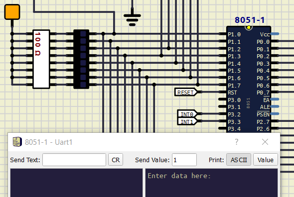
However, when I try to send data to the MCU from the Monitor (e.g. the number "1" + Enter so the LED on P1.0 is set to low), it doesn't work.
For the MCU to receive something from the Monitor, I need to connect something to P3.0, then it works (in the example below I'm connecting P3.0 to a GND, just to connect something...:

So, if I understand what you said, this is how it's supposed to work? To send something from the MCU to the Monitor I don't need to connect anything, but to send something from the Monitor to the MCU I need to connect something to the RX pin.
Thanks!
I don't understand what you exactly mean by "not working".
There is an optimization to save some cpu: if Uart pins are not connected, then all the bit banging routine is skipped.
But Serial Monitor still works, so you can see what the MCU is sending or send data to the MCU from the Monitor.
So Uart should work in both cases, but if nothing connected then nothing goes to the pins.
Or at least that is how it should work.
Sorry for not making it clear.
This is what I meant:
When I load program 17, without connecting anything to P3.0 (RX pin), the MCU sends "Enter data here" through the UART, without any problem as you said:
However, when I try to send data to the MCU from the Monitor (e.g. the number "1" + Enter so the LED on P1.0 is set to low), it doesn't work.
For the MCU to receive something from the Monitor, I need to connect something to P3.0, then it works (in the example below I'm connecting P3.0 to a GND, just to connect something...:
So, if I understand what you said, this is how it's supposed to work? To send something from the MCU to the Monitor I don't need to connect anything, but to send something from the Monitor to the MCU I need to connect something to the RX pin.
Thanks!
38 Re: 8051 - The CNJE instruction with Registers make the simulation stop Mon Jan 16, 2023 12:45 am
diego_souza
Everything looks correct to me.
50.000 cycles * 20 = 1 seg at 12 MHz, little bit more at 11.0592 MHz.
You are absolutely right.
I should have used:
Mov TH0,#04BH
Mov TL0,#0FDH
instead of
Mov TH0,#03CH
Mov TL0,#0B0H
Now it works perfectly. Thanks!

50.000 cycles * 20 = 1 seg at 12 MHz, little bit more at 11.0592 MHz.
You are absolutely right.
I should have used:
Mov TH0,#04BH
Mov TL0,#0FDH
instead of
Mov TH0,#03CH
Mov TL0,#0B0H
Now it works perfectly. Thanks!
arcachofo likes this post
39 Re: 8051 - The CNJE instruction with Registers make the simulation stop Mon Jan 16, 2023 1:01 am
arcachofo
Ok, now I understand. Thanks for the detailed explanations.However, when I try to send data to the MCU from the Monitor (e.g. the number "1" + Enter so the LED on P1.0 is set to low), it doesn't work.
For the MCU to receive something from the Monitor, I need to connect something to P3.0, then it works (in the example below I'm connecting P3.0 to a GND, just to connect something...:
No no... Serial Monitor should always work.So, if I understand what you said, this is how it's supposed to work? To send something from the MCU to the Monitor I don't need to connect anything, but to send something from the Monitor to the MCU I need to connect something to the RX pi
So this is an error, I will have a look.
40 Re: 8051 - The CNJE instruction with Registers make the simulation stop Mon Jan 16, 2023 2:13 pm
arcachofo
Solved at Rev 1211.However, when I try to send data to the MCU from the Monitor (e.g. the number "1" + Enter so the LED on P1.0 is set to low), it doesn't work.
For the MCU to receive something from the Monitor, I need to connect something to P3.0, then it works (in the example below I'm connecting P3.0 to a GND, just to connect something...:
41 Re: 8051 - The CNJE instruction with Registers make the simulation stop Mon Jan 16, 2023 8:49 pm
diego_souza
Thanks!
Where can I download Rev 1211?
Diego
Where can I download Rev 1211?
Diego
42 Re: 8051 - The CNJE instruction with Registers make the simulation stop Tue Jan 17, 2023 9:39 am
arcachofo
I will upload new executables soon.
43 Re: 8051 - The CNJE instruction with Registers make the simulation stop Tue Jan 17, 2023 2:06 pm
diego_souza
Hi,
I'm doing some tests with the code editor and the ASEM.exe, and here are some comments:
1. First, I need to change the asem51.xml command to "ASEM.exe", which is expected and you explained.
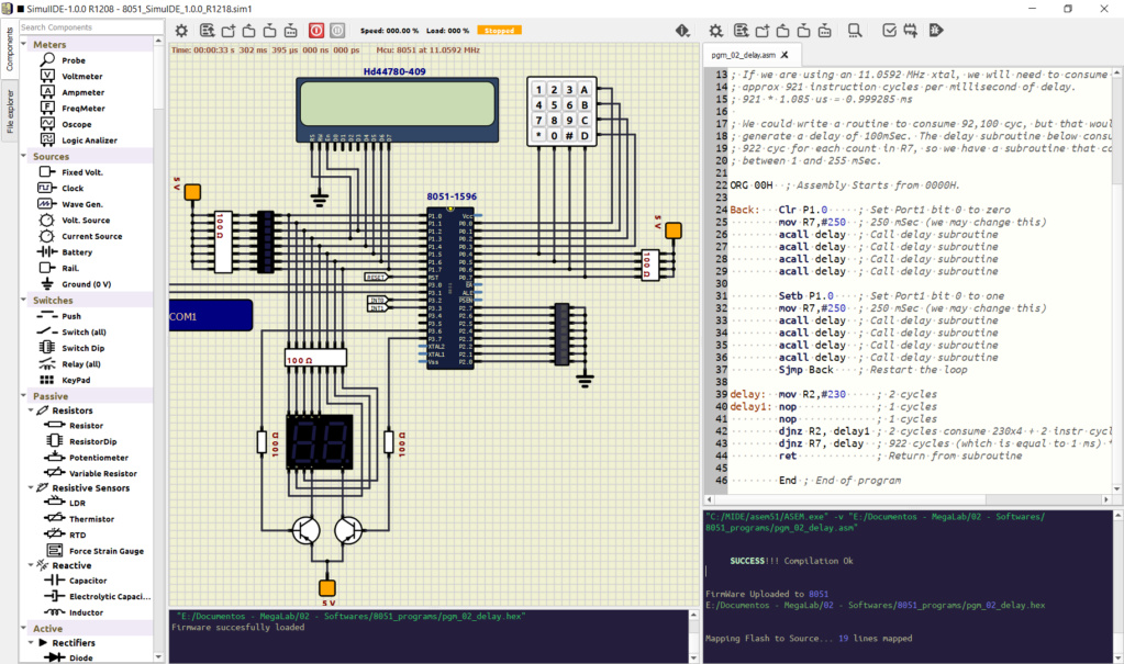
2. Then, I loaded "pgm_02_delay.asm" in the editor, and it opened OK.
3. When I click "Compile", the terminal says "SUCCESS - Compilation OK". However, if I check the hex file creation time, it didn't change.
4. When I click "Upload", the terminal says "FirmWare Uploaded to 8051" and "Mapping Flash to Source... 19 lines mapped" but the firmware is not changed in the simulation (as I said, the hex file creation time hasn't changed). To make a test, I changed the number of calls to the "delay" subroutine, and the program was not changed.
Please find an image below. I wonder if it has to do with the spaces in my directory names:
I'm doing some tests with the code editor and the ASEM.exe, and here are some comments:
1. First, I need to change the asem51.xml command to "ASEM.exe", which is expected and you explained.
2. Then, I loaded "pgm_02_delay.asm" in the editor, and it opened OK.
3. When I click "Compile", the terminal says "SUCCESS - Compilation OK". However, if I check the hex file creation time, it didn't change.
4. When I click "Upload", the terminal says "FirmWare Uploaded to 8051" and "Mapping Flash to Source... 19 lines mapped" but the firmware is not changed in the simulation (as I said, the hex file creation time hasn't changed). To make a test, I changed the number of calls to the "delay" subroutine, and the program was not changed.
Please find an image below. I wonder if it has to do with the spaces in my directory names:
44 Re: 8051 - The CNJE instruction with Registers make the simulation stop Tue Jan 17, 2023 2:10 pm
diego_souza
Hi,
It's not related to spaces in the dir name, made a new test in a new dir and the situation is the same, the hex file is not created and the firmware is not updated in the MCU.
It's not related to spaces in the dir name, made a new test in a new dir and the situation is the same, the hex file is not created and the firmware is not updated in the MCU.
45 Re: 8051 - The CNJE instruction with Registers make the simulation stop Tue Jan 17, 2023 2:19 pm
diego_souza
Here are a couple of suggestions for v 1.0.0 (not related to 8051):
1. Add one 40 pin ATMega MCU (like ATMega32).
2. Add one 20 pin Attiny (like ATtiny2313).
3. Add the possibility to change the Editor colors in the Editor Settings, so we can build and share new color schemes.

Thanks!
1. Add one 40 pin ATMega MCU (like ATMega32).
2. Add one 20 pin Attiny (like ATtiny2313).
3. Add the possibility to change the Editor colors in the Editor Settings, so we can build and share new color schemes.
Thanks!
46 Re: 8051 - The CNJE instruction with Registers make the simulation stop Tue Jan 17, 2023 3:15 pm
diego_souza
Another suggestion:
- Save the compiler settings and the latest program loaded in the editor, so when I close SimulIDE, open it again and open a "sim1" file, it automaticaly loads the compiler settings and program that were loaded when I saved the file.
- Save the compiler settings and the latest program loaded in the editor, so when I close SimulIDE, open it again and open a "sim1" file, it automaticaly loads the compiler settings and program that were loaded when I saved the file.
47 Re: 8051 - The CNJE instruction with Registers make the simulation stop Tue Jan 17, 2023 3:57 pm
arcachofo
Hi, let's go by parts:
About compiling:
Note that simulide does not compile anything, it just executes the commands provided in compiler xml file.
If there is no error messages it assumes that the compilation was ok.
The output of the compiler is shown in the bottom panel.
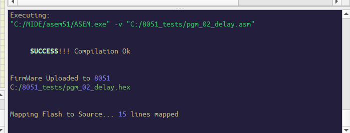
For example in my system:

I don't see any messages from ASEM.exe in your case, looks like it is doing nothing...
So there is some problem with that command.
You need to find which command works in your system.
About suggestions:
Note that 1.0.0 is already 2 versions behind the development version.
1. Add one 40 pin ATMega MCU (like ATMega32).
2. Add one 20 pin Attiny (like ATtiny2313).
AVR Devices added since 1.0.0:
ATtiny: 2313, 4313
ATmega: 16, 32, 164, 324, 644, 1284
3. Add the possibility to change the Editor colors in the Editor Settings, so we can build and share new color schemes.
You can change or add syntax files here: data/codeeditor/syntax
And choose a syntax file in compiler xml file.
- Save the compiler settings and the latest program loaded in the editor, so when I close SimulIDE, open it again and open a "sim1" file, it automaticaly loads the compiler settings and program that were loaded when I saved the file.
There is a "recent files" button in the tool bar, you can open the last one there.
You can define which compiler to use in a comment in the first line of the asm file (have a look at the image above).
About compiling:
Note that simulide does not compile anything, it just executes the commands provided in compiler xml file.
If there is no error messages it assumes that the compilation was ok.
The output of the compiler is shown in the bottom panel.
For example in my system:

I don't see any messages from ASEM.exe in your case, looks like it is doing nothing...
So there is some problem with that command.
You need to find which command works in your system.
About suggestions:
Note that 1.0.0 is already 2 versions behind the development version.
1. Add one 40 pin ATMega MCU (like ATMega32).
2. Add one 20 pin Attiny (like ATtiny2313).
AVR Devices added since 1.0.0:
ATtiny: 2313, 4313
ATmega: 16, 32, 164, 324, 644, 1284
3. Add the possibility to change the Editor colors in the Editor Settings, so we can build and share new color schemes.
You can change or add syntax files here: data/codeeditor/syntax
And choose a syntax file in compiler xml file.
- Save the compiler settings and the latest program loaded in the editor, so when I close SimulIDE, open it again and open a "sim1" file, it automaticaly loads the compiler settings and program that were loaded when I saved the file.
There is a "recent files" button in the tool bar, you can open the last one there.
You can define which compiler to use in a comment in the first line of the asm file (have a look at the image above).
48 Re: 8051 - The CNJE instruction with Registers make the simulation stop Tue Jan 17, 2023 6:09 pm
diego_souza
I don't see any messages from ASEM.exe in your case, looks like it is doing nothing...
You're right! I tried to execute the ASEM.exe in the command prompt and it says it is not compatible with my Windows version... I have tried running it using the compatibility mode and had no success. I don't know how M-IDE studio can execute it in this machine. I'll keep looking for a solution.
Thanks for the other clarifications.
49 Re: 8051 - The CNJE instruction with Registers make the simulation stop Wed Jan 18, 2023 10:22 am
arcachofo
I have no idea, but maybe M-IDE has it's own executables, like Arduino has it's own avr-gcc and other avr tools.I don't know how M-IDE studio can execute it in this machine.
You can probably see which command it executes when compiling.
50 Re: 8051 - The CNJE instruction with Registers make the simulation stop Wed Jan 18, 2023 3:56 pm
diego_souza
The curious thing is that I tested with both options:
- The executable from the ASEM-51 webpage:
http://plit.de/asem-51/download.htm
- The executable from MIDE-51, as in the screenshot below. In the end they are the same. But I don't have any idea on how MIDE-51 manages to execute it.
I'll keep searching...

- The executable from the ASEM-51 webpage:
http://plit.de/asem-51/download.htm
- The executable from MIDE-51, as in the screenshot below. In the end they are the same. But I don't have any idea on how MIDE-51 manages to execute it.
I'll keep searching...
![]() Message [Page 2 of 3]
Message [Page 2 of 3]
Go to page : ![]() 1, 2, 3
1, 2, 3 ![]()
» Discussions About SimulIDE Simulator » Report Bugs » 8051 - The CNJE instruction with Registers make the simulation stop
Similar topics
![]()
Permissions in this forum:
You cannot reply to topics in this forum