Hello arcachofo,
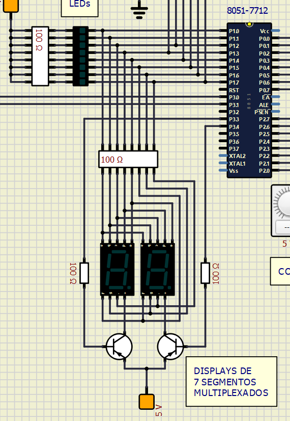
Please fin the asm program below. I'm multiplexing two 7-segment displays.
- Code:
; This program multiplexes a 00 to 99 counter
; on two 7-segment displays with an specific
; time interval.
; Note: a logic 0 lights a display segment.

ORG 0000H     ; Assembly starts from 0000H.

Mov DPTR,#LUT ; DPTR points to the start of the lookup table
MOV R0,#00H     ; Init the tens
MOV R1,#00H     ; Init the ones
Mov R3,#00H     ; Init our time reference

main:

back:
    CLR P3.3      ; Enable display 1
    SETB P3.4     ; Disable display 2

    MOV A,R0      ; Digit to show on display 1
    ACALL DISPLAY ; Show the digit

    MOV R7,#5     ; 5 ms interval
    ACALL Delay   ; Call the delay subroutine

    SETB P3.3     ; Disable display 1
    CLR P3.4      ; Enable display 2

    MOV A,R1      ; Digit to show on display 2
    ACALL DISPLAY ; Show the digit

    MOV R7,#5      ; 5 ms interval
    ACALL Delay    ; Call the delay subroutine

    INC R3              ; Increment R3 (our time reference)
    MOV A, R3           ; Pass R3 to A (for some reason CJNE with R doesn't work on SIMULIDE)
    CJNE A,#100, back   ; If R3 is not equal to 100 (100 x 2 x 5 ms = 1s), jump to back
    Mov R3,#0           ; If R3 is equal to 100, reset our time reference
    INC R1              ; and increment R1 (ones)
    MOV A, R1           ; Pass R1 to A (for some reason CJNE with R doesn't work on SIMULIDE))
    CJNE A,#10, back    ; If R1 (ones) is not equal to 10, jump to back
    MOV R1,#0           ; If R1 (ones) is equal to 10, zero the ones
    INC R0              ; and increment R0 (tens)
    MOV A, R0           ; Pass R0 to A (for some reason CJNE with R doesn't work on SIMULIDE)
 CJNE A,#10, back    ; If R0 (tens) is not equal to 10, jump to back
    MOV R0,#0           ; If R0 (tens) is equal to 10, zero the tens

    SJMP main           ; Jump back to the start

DISPLAY: MOVC A,@A+DPTR ; Gets digit drive pattern for the current value from LUT
         MOV P1,A       ; Puts corresponding digit drive pattern into P1
         RET            ; Return from subroutine

delay:  MOV R2,#230     ; 2 cycles
delay1: NOP             ; 1 cycles
        NOP             ; 1 cycles
        DJNZ R2, delay1 ; 2 cycles consume 230x4 + 2 instr cycles = 922 cycles
        DJNZ R7, delay  ; 922 cycles (which is equal to 1 ms) * number of counts in R7
        RET             ; Return from subroutine

ORG 0200h
LUT:    DB 0C0h, 0F9h, 0A4h, 0B0h, 99h, 92h, 82h, 0F8h, 80h, 90h, 0
END ; End of Program
And this is the circuit I'm using:
The problem is that, when I use the CJNE instruction with a register, like this:
- Code:
INC R3              ; Increment R3 (our time reference)
CJNE R3,#100, back  ; If R3 is not equal to 100 (100 x 2 x 5 ms = 1s), jump to back
This works in a real circuit but doesn't work in SimuIDE (the display n° 1 doesn't show anything and the display n°2 keeps showing a 0. Also, P3.3 and P3.4 doesn't toogle and thus the displays are not multiplexed). In fact, they toogle a single time and stop.
However, if I change the code to:
- Code:
INC R3              ; Increment R3 (our time reference)
MOV A, R3           ; Pass R3 to A (for some reason CJNE with R doesn't work on SIMULIDE)
CJNE A,#100, back   ; If R3 is not equal to 100 (100 x 2 x 5 ms = 1s), jump to back
Then, it works well.
Another problem I have with the 8051 simulation in SimulIDE is regarding the software delays (which I'm also using in the 7 seg multiplex example).
My millisecond delay subroutine looks like this (I'm using a 11.0592 MHz crystal, both in my real circuit and the simulation):
In this example, with R7 I select how many milliseconds I want the routine to delay.
- Code:
; Crystal frequency: 11.0592 MHz
; The 8051 uses 1/12 of oscilator frequency. So the frequency is:
; 11.0592 / 12 = 921.6 kHz
; The cycle execution time becomes 1/f = 1/921.6kHz = 1.085uS per cycle. So the
; Desired time = Total Cycles * 1.085 us

; If we are using an 11.0592 MHz xtal, we will need to consume
; approx 921 instruction cycles per millisecond of delay.
; 921 * 1.085 us = 0.999285 ms

; We could write a routine to consume 92,100 cyc, but that would only
; generate a delay of 100mSec. The delay subroutine below consumes
; 922 cyc for each count in R7, so we have a subroutine that can delay
; between 1 and 255 mSec.

ORG 00H  ; Assembly Starts from 0000H.

Back:   Clr P1.0     ; Set Port1 bit 0 to zero
 mov R7,#250  ; 250 mSec (we may change this)
        acall delay  ; Call delay subroutine
        acall delay  ; Call delay subroutine
 acall delay  ; Call delay subroutine
        acall delay  ; Call delay subroutine
        Setb P1.0    ; Set Port1 bit 0 to one
        mov R7,#250  ; 250 mSec (we may change this)
        acall delay  ; Call delay subroutine
        acall delay  ; Call delay subroutine
        acall delay  ; Call delay subroutine
        acall delay  ; Call delay subroutine
        Sjmp Back    ; Restart the loop

delay:  mov R2,#230     ; 2 cycles
delay1: nop             ; 1 cycles
        nop             ; 1 cycles
        djnz R2, delay1 ; 2 cycles consume 230x4 + 2 instr cycles = 922 cycles
        djnz R7, delay  ; 922 cycles (which is equal to 1 ms) * number of counts in R7
        ret             ; Return from subroutine

        End ; End of program
However, when simulating with SimulIDE and cheking with the oscilloscope I see that the interval is approximatelly 2.3 times longer than expected (so the 1 s total delay from the example above takes 2.3 s aproximatelly).
In a real circuit I have 1 s exactly, and on the simulation I have 2.3 s aproximatelly.
For the simulation to match the exact milliseconds, in my subroutine I have to change R2 from 230 to 102, like this:
- Code:
delay:  MOV R2,#102     ; 2 cycles
delay1: NOP             ; 1 cycles
        NOP             ; 1 cycles
        DJNZ R2, delay1 ; 2 cycles consume 230x4 + 2 instr cycles = 922 cycles
        DJNZ R7, delay  ; 922 cycles (which is equal to 1 ms) * number of counts in R7
        RET             ; Return from subroutine
Then, I have the exact number of milliseconds defined on R7 in the simulation.
Any hints?
Thanks!

 Latest images


