Would you like to react to this message? Create an account in a few clicks or log in to continue.

You are not connected. Please login or register

HW I2C / TWI on AVR kind of not working on IC-pin

2 posters

Go down  Message [Page 1 of 1]

TimFisch

TimFisch

I tried to use hardware TWI of the ATmega328 on simulide 0.5.15, but it seems that the output on pin level is not completely correct.

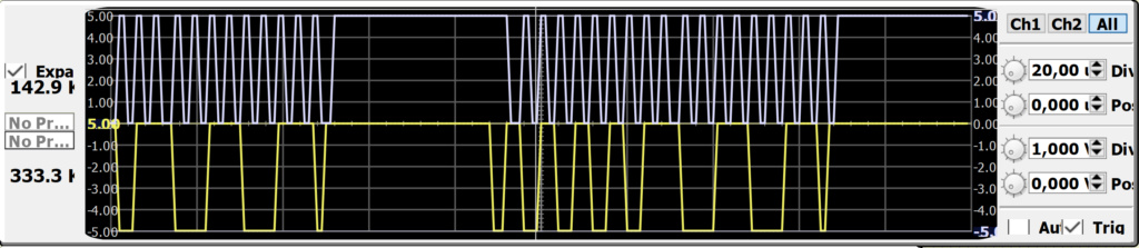
The resulting signals are shown in the following image (SCL in brightblue on top, SDA in yellow on bottom). The SCL seems a bit delayed and the start condition of TWI is not correctly set before the the first rising edge.

I used the internal TWI registers without the TWI interrupt, only with polling, as shown in the 328 datasheet.

HW I2C / TWI on AVR kind of not working on IC-pin  I2c10

https://wiki.mexle.hs-heilbronn.de/

arcachofo

arcachofo

Looks like that is RC1...

If so, the oscope channels are not synchonized. then the two signal are at diferent times.
Since RC2 it is possible to see both channels synchronized, but it is still too buggy to be useful.

TimFisch

TimFisch

Thank for the feedback.

I just tried it with the RC2, too - but the situation there is not really better.
I was not able to get any TWI signal at the first try with the same SW/HW setup. The scope is black. The signal line indicate, that the level is always high, so the pull-ups are working. The MCU TWI output seems not to work.

When deleting anything (seems not to matter what, does not neet to be related with TWI) and undo this step, the signal lines and the scope shows some signal. However, I was not able to see a full 9bit TWI trace, only single edges.

I'm not able to change the time division correctly (it seem to jump back to the shown value, when inserting different numbers).

Strange ...silent

https://wiki.mexle.hs-heilbronn.de/

arcachofo

arcachofo

Yes... RC2 is not very usable.
Oscope has a few problems to solve and avr twi i don't even know if it's doing something .
It will take some time to get everithing working 100%.

arcachofo

arcachofo

I forgot to mention that there is always the posibility to use software I2C.

Also to say that there is a new feature for oscope in coming RC3.
It takes an "snapshot" on certain conditions of the inputs.

For example here watching I2C (software) sending slave address.
Conditions are: CH2=High (scl), and CH1=Rising (sda), this is Stop Condition.
When condition is met, Oscope pauses the simulation and shows an snapshot of the last x microseconds (configurable).

HW I2C / TWI on AVR kind of not working on IC-pin  Oscope10


This will help me to debug a few things, and will be useful in cases like this post.

PD: i'm still wondering how did you manage to get the capture in your first post...

TimFisch

TimFisch

Thanks for the feedback. I will implement for the first step as soft I2C. However, since I try to explain the I2C with registers to the student I eagerly wait for the progress ;-)

The new scope looks better and better.

My image was done by slowing down the simulation, twaeking the simulation steps and triggering the hardware I2C with a button (and trying multiple times..). More a trial and error game..

https://wiki.mexle.hs-heilbronn.de/

Sponsored content


Back to top  Message [Page 1 of 1]

Permissions in this forum:
You cannot reply to topics in this forum