Would you like to react to this message? Create an account in a few clicks or log in to continue.

You are not connected. Please login or register

555 circuit problem or SimulIDE problem.... or is it me the problem?

5 posters

Go down  Message [Page 1 of 1]

blitobyte

blitobyte

Hi,

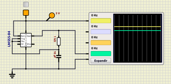
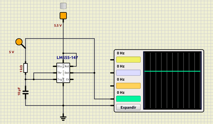
I'm doing a 555 course and according to the teacher, the circuit I'm sending you should give this result, but in fact it doesn't on SimulIDE. What am I doing wrong?
Attachments
555 circuit problem or SimulIDE problem.... or is it me the problem? Attachmentt10_el_mas_simple.sim1.zip
SImulIDE circuit
You don't have permission to download attachments.
(2 Kb) Downloaded 8 times

ci@telemack.net


In any case I am not sure why the output would give only 3.3v when vcc is at 5v [EDIT see answer below...]

I have the same result than the proto on multisim with a simplified 555 breakout.
Attachments
555 circuit problem or SimulIDE problem.... or is it me the problem? Attachmentlm555-test1.zip
You don't have permission to download attachments.
(3 Kb) Downloaded 4 times


Last edited by ci@telemack.net on Sat Apr 15, 2023 2:08 pm; edited 1 time in total

Defran

Defran

To make it oscillate, you have to connect "dis" to "thr. Dis discharges the capacitor (dis=discharge).

3.3V is ok, if you need more volts you have to connect a buffer driver to the output.

KerimF

KerimF

In the conventional 555 (as NE555), the drop voltage when its output is high is about 2*Vbe (it depends on the load and temperature).

555 circuit problem or SimulIDE problem.... or is it me the problem? Ne555s10

This drop is much lower in CMOS 555. The output voltage could be very close to Vcc, but not equal (equal if output current=0).

ci@telemack.net


Ok thanks a lot - this is what the TI datasheets say indeed.
But in any case the schematic works irl as intended - tested with TI NE555 (but TI says LM555 is a direct replacement - not sure what this implies exactly beyond being pin compatible)
So there is something fishy imho  555 circuit problem or SimulIDE problem.... or is it me the problem? 1f41f

scratch

(pic available for the unfaithfull :-)
To sum up :
1) if the IC modeled is really the LM555, it should output 4v < n <5v if vcc = 5v
As per TI datasheet :
Output Voltage Drop (Low) VCC = 5 V 0.25 typ 0.35 max
2) it looks like the output is at high z but does not sink current when low, so cannot discharge the capacitor as it should. Just a wild guess :-)


Last edited by ci@telemack.net on Sat Apr 15, 2023 7:29 pm; edited 2 times in total

blitobyte

blitobyte

Defran wrote:To make it oscillate, you have to connect "dis" to "thr. Dis discharges the capacitor (dis=discharge).

3.3V is ok, if you need more volts you have to connect a buffer driver to the output.

Hi Defran. I'm sorry but in my version (1.0.0-SR01320), even if I connect "dis" to "thr" it doesn't work. Did you check the attached file?

7555 circuit problem or SimulIDE problem.... or is it me the problem? Empty About TI schematic Sun Apr 16, 2023 4:00 pm

ci@telemack.net


Hello KarimF,
I am looking at the TI schematic, but I confess I am not experienced enough to be sure about how to correctly interpret the 'third' connection on Q5, Q6 and Q22.

Any idea where exactly it connects on the transistor ? I am at a loss here...

Defran

Defran

Use the 555 that is in menu "Other IC", and use the option LS, it is more instructive.

KerimF

KerimF

ci@telemack.net wrote:Hello KarimF,
I am looking at the TI schematic, but I confess I am not experienced enough to be sure about how to correctly interpret the 'third' connection on Q5, Q6 and Q22.

Any idea where exactly it connects on the transistor ? I am at a loss here...

Me too, I am not expert in IC design. But a quick analysis of the circuit shows that the current of the Q5 and Q6 emitters are limited by R1 (when one of them is on). So, their third connection is simply an extra internal collector so that their emitter current could be divided, at a certain ratio, in two paths while their sum is limited by R1. This lets the base currents of Q15, Q16 and Q17 be limited too. In other words, Q5 and Q6 could be seen as controlled active loads of Q15 and Q16.
Q22 is likely for resetting 555 when RESET pin is lower than Vbe (usually grounded). Here again, the second collector works as an active load of Q20.

I wonder if, by searching, we can also find a discrete bjt (NPN or PNP transistor) with two separate collectors.

blitobyte

blitobyte

Defran wrote:Use the 555 that is in menu "Other IC", and use the option LS, it is more instructive.

It doesn't matter which 555 I use. Both behave in the same way. They won't oscillate. I'm including the file with the new 555.
Attachments
555 circuit problem or SimulIDE problem.... or is it me the problem? Attachmentt10_el_mas_simple_1.sim1.zip
Using the 555 in Other IC
You don't have permission to download attachments.
(2 Kb) Downloaded 2 times

ci@telemack.net


KerimF wrote:
I wonder if, by searching, we can also find a discrete bjt (NPN or PNP transistor) with two separate collectors.

Thanks for the precious insight - and indeed :

https://en.wikipedia.org/wiki/Multiple-emitter_transistor

Defran

Defran

555 circuit problem or SimulIDE problem.... or is it me the problem? T10_el10
Attachments
555 circuit problem or SimulIDE problem.... or is it me the problem? Attachmentt10_el_mas_simple_1a.zip
You don't have permission to download attachments.
(2 Kb) Downloaded 2 times

blitobyte

blitobyte

Defran wrote:555 circuit problem or SimulIDE problem.... or is it me the problem? T10_el10

I'm afraid we're talking about different circuits. In mine 'Out' goes to the resistor. Sort of retro feed-back. In yours the resistor is connected to PWR. Obviously, yours, is clearly oscillating. The problem is that mine (my teacher's proposal) woks as expected in Multisim on-line but not in SimulIDE.
555 circuit problem or SimulIDE problem.... or is it me the problem? My_cir10

Defran

Defran

Hi,

Feeding the 555 at 5V the internal comparators need a little more than 3.3v for the HIGH level in "Out" for the feedback, so an external resistor helps to rise this value. In the reality this can happen also depending the manufacturing technology and the manufacturer.

555 circuit problem or SimulIDE problem.... or is it me the problem? T10_el11

Resistor and diode to separate carge and discharge...

555 circuit problem or SimulIDE problem.... or is it me the problem? T10_el12

Adding a buffer...

555 circuit problem or SimulIDE problem.... or is it me the problem? T10_el14

It is also obtained by slightly raising the supply voltaje to the 555 which can work between 4.5 and 15v.

555 circuit problem or SimulIDE problem.... or is it me the problem? T10_el13

Conclusion. 555 was designed around 1976 when the prevailing technique was TTL, whose the logical values are 0 to 0.8V for LOW and 2.4 to 5V for HIGH, according to this the 555 of Simulide meets the specifications, since feeding it at 5v it gives 3.3v minimum for HIGH. On the other hand, 555 was not designed to work accurately in feedback, that's why added the discharge pin (Dis), avoiding feedback.

In the section "Projects Made in Simulide" of this same website you have many examples of use of the 555 if you want to see more practical appliction circuits of this old but successful 555. And I repeat: use always the symbol 555 option LS, it is more clear.

Best regards.

blitobyte

blitobyte

Defran wrote:Hi,

Feeding the 555 at 5V the internal comparators need a little more than 3.3v for the HIGH level in "Out" for the feedback, so an external resistor helps to rise this value. In the reality this can happen also depending the manufacturing technology and the manufacturer.

555 circuit problem or SimulIDE problem.... or is it me the problem? T10_el11

Resistor and diode to separate carge and discharge...

555 circuit problem or SimulIDE problem.... or is it me the problem? T10_el12

Adding a buffer...

555 circuit problem or SimulIDE problem.... or is it me the problem? T10_el14

It is also obtained by slightly raising the supply voltaje to the 555 which can work between 4.5 and 15v.

555 circuit problem or SimulIDE problem.... or is it me the problem? T10_el13

Conclusion. 555 was designed around 1976 when the prevailing technique was TTL, whose the logical values are 0 to 0.8V for LOW and 2.4 to 5V for HIGH, according to this the 555 of Simulide meets the specifications, since feeding it at 5v it gives 3.3v minimum for HIGH. On the other hand, 555 was not designed to work accurately in feedback, that's why added the discharge pin (Dis), avoiding feedback.

In the section "Projects Made in Simulide" of this same website you have many examples of use of the 555 if you want to see more practical appliction circuits of this old but successful 555. And I repeat: use always the symbol 555 option LS, it is more clear.

Best regards.

Hi Defran,
lots, lots and lots of thanks for your answers, theoretical explanations and interest in my problem. I understand that you are suggesting ways to improve the circuit and so on, but unfortunately you're not solving my question. The question is if the 'circuit' I sent, the one suggested by my teacher, is handled by SimulIDE properly or not. If I compare the solution given to it by SimulIDE and Multisim online they don't coincide, and as a matter of fact, Multisim and my teacher did, so my first thought was: SimulIDE has a bug here!!! That's the point. Does it have it?
If I could use Proteus, but I cannot, I use Linux, I could compare with it.

On the other hand I've observed that your 555 has a different layout, (mind the pins) from mine. Here are the two I have in SimulIDE:

555 circuit problem or SimulIDE problem.... or is it me the problem? Captur10

Might that be the cause?

blitobyte

blitobyte

Hi again Defran,

I found your 555 subcircuit in SimulIDE R1618. I was using the official release R1320.

This is mine:

555 circuit problem or SimulIDE problem.... or is it me the problem? Captur11

As you can see it doesn't coincide with yours. Perhaps you set up the 555 in a special way? That could be the reason, otherwise....

Defran

Defran

Well, About the difference between Simulide and other simulation programs (there may be hundreds) I can't tell you anything because i don't know them. I refer to what I told you: Simulide complies with the TTL output specifications. See if in Multisim, for instance, it gives different output voltages compared to Simulide, i think that's where the problem is in this case, as I have explained in the previous post.

Regarding the aesthetic differences in the components, they may depend on the version of the program, in the 555, the important thing is that the name of the pins is the same.

About the version of simulide, I recomend use the last one of SIMULIDE TRUNK, it is the most advanced version with more features. It is true that it is a beta version, but it has very very few bugs that do not affect its regular use and if you see any you should notify Simulide. I only use Trunk.

blitobyte

blitobyte

Defran wrote:Well, About the difference between Simulide and other simulation programs (there may be hundreds) I can't tell you anything because i don't know them. I refer to what I told you: Simulide complies with the TTL output specifications. See if in Multisim, for instance, it gives different output voltages compared to Simulide, i think that's where the problem is in this case, as I have explained in the previous post.

Regarding the aesthetic differences in the components, they may depend on the version of the program, in the 555, the important thing is that the name of the pins is the same.

About the version of simulide, I recomend use the last one of SIMULIDE TRUNK, it is the most advanced version with more features. It is true that it is a beta version, but it has very very few bugs that do not affect its regular use and if you see any you should notify Simulide. I only use Trunk.

I think I found the problem. My circuits were powered with 5V. The moment I increased it slightly, from 5.1V on, the 555 started to oscillate.

One more thing. I'm using RC1618. You suggest using the last trunk version, at the moment 1648 I think. Ddo you know if I can get it already compiled or do I have to compile it myself? I got RC1618 already compiled.

Thanks a lot!!!

Defran

Defran

R1618 is the last one. It is ok.

arcachofo

arcachofo

This issue is related to the output voltage, which depends on various factors.
It is not very accurate in Simulide, but much more than Multisim simulation in the link: https://www.multisim.com/content/UnNmdb5YkB5KuhRHbhkNKh/t10_el_mas_simple/open/

Voltage drop is determined by the output stage (Vdrop at Q27 + Vdrop at  Q28):
555 circuit problem or SimulIDE problem.... or is it me the problem? 55511


Output voltage as per Texas Instruments LM555 datasheet:

555 circuit problem or SimulIDE problem.... or is it me the problem? 555-210

As you can see, Vout never reaches Vcc even in the best case.
Simulide uses the worst case scenario (1.7 V voltage drop), but it probably should use voltage drop at 20º C or something like that, then this circuit should work.

blitobyte

blitobyte

arcachofo wrote:This issue is related to the output voltage, which depends on various factors.
It is not very accurate in Simulide, but much more than Multisim simulation in the link: https://www.multisim.com/content/UnNmdb5YkB5KuhRHbhkNKh/t10_el_mas_simple/open/

Voltage drop is determined by the output stage (Vdrop at Q27 + Vdrop at  Q28):
555 circuit problem or SimulIDE problem.... or is it me the problem? 55511


Output voltage as per Texas Instruments LM555 datasheet:

555 circuit problem or SimulIDE problem.... or is it me the problem? 555-210

As you can see, Vout never reaches Vcc even in the best case.
Simulide uses the worst case scenario (1.7 V voltage drop), but it probably should use voltage drop at 20º C or something like that, then this circuit should work.

Ok. I see what you mean. Thanks

Defran

Defran

Arcahofo, Nice improvement in T1657, thanks.


Last edited by Defran on Fri Apr 28, 2023 10:43 pm; edited 1 time in total

arcachofo likes this post

Sponsored content


Back to top  Message [Page 1 of 1]

Permissions in this forum:
You cannot reply to topics in this forum