Would you like to react to this message? Create an account in a few clicks or log in to continue.

You are not connected. Please login or register

Resistor problem

2 posters

Go down  Message [Page 1 of 1]

1Resistor problem Empty Resistor problem Sun Sep 05, 2021 11:13 am

jbs30000


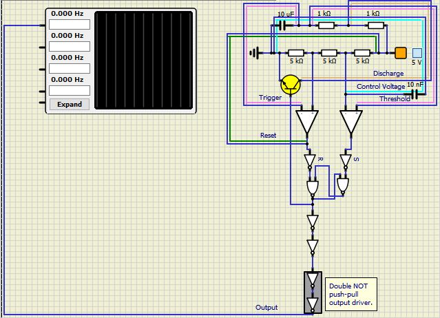
I'll spare you the boring details as to why I'm making a 555 timer when one's already included.  I will say I constructed my own SR latch because I'm testing this on 4.15 and 4.14, and 4.14 doesn't seem to have the SR latch that's built into the 4.15.
Anyway, after setting up the 555 as an astable timer and running it, power that goes into the first 1K resistor doesn't come out to the other side(I found this out by turning the animation on).  Well, sometimes.  I'll make a change, and then it runs, and then a few tries later it stops working again.  For example, the first 1K resistor was actually 100K.  Lowering to 1K worked for a while.  Then I tried something needless like making the power going to the "reset" go through a diode.  Again, worked for a little while.
The problem is either something simple I'm missing, or it could just be the emulation.  For example, the last time I tried it on 4.15 and got it to run, I turned of the 5V power supply, but the 555 kept running as if I hadn't.
I included a picture and the .simu file, so if you see any bone-headed mistakes, please let me know.  And thanks.
Resistor problem Tmp10
Attachments
Resistor problem AttachmentLM5.zip
You don't have permission to download attachments.
(5 Kb) Downloaded 1 times

2Resistor problem Empty Re: Resistor problem Sun Sep 05, 2021 9:38 pm

arcachofo

arcachofo

Hi.

First, about the SR latch, you can use a JK as an SR (just connect the S and R pins and leave the other pins unconnected).

About the circit, the first problem I see is that the 5V source is connected directly to the Op-Amp output on the left.

Then as recomendations:
- Use a mosfet instead of a BJT for switching, the simulation will run much faster.
- Those 4 inverters at the output can be substituted by a single buffer.
- Use a flipflop instead of a gated SR.

EDIT:
Another problem is that you are taking the inverted output of the SR for the discharge transistor, you should use the other one.

Also, if you still want to use a BJT , you should add a base resistor.
Without resistor, base voltage will not go higher that 0.7 V in the simulation, in real world you will probably burn that transistor.


3Resistor problem Empty Re: Resistor problem Mon Sep 06, 2021 3:19 am

jbs30000


Thank you very much.  As for,
Arcachofo wrote:About the circit, the first problem I see is that the 5V source is connected directly to the Op-Amp output on the left.
The 5V is supposed to go after the inverter.  After making my own latch, then switching to a built in one, then going back to my own I accidentally connected the reset to the Op-Amp output.Resistor problem Smack
As for,
Another problem is that you are taking the inverted output of the SR for the discharge transistor, you should use the other one.
OK.  All the schematics I look at show the discharge coming from the inverted output of the S/R latch.  But then again I've been discovering that a lot of schematics, even those in datasheets, aren't always the most accurate.

4Resistor problem Empty Re: Resistor problem Mon Sep 06, 2021 5:41 am

arcachofo

arcachofo

OK.  All the schematics I look at show the discharge coming from the inverted output of the S/R latch.  But then again I've been discovering that a lot of schematics, even those in datasheets, aren't always the most accurate.
Yes there are lots of variations.
And block diagrams are always an abstraction of the real circuit and can be done in diferent ways.

For example in this one, discharge is connected to the inverted output of the SR.
But trigger is connected to the "S" input of the SR.

Resistor problem Sr55510


But your circuit is similar to this one:
In this one the non-inverted output is used, but trigger goes to "R".

Resistor problem Sr555-10

5Resistor problem Empty Re: Resistor problem Mon Sep 06, 2021 8:23 am

jbs30000


To be honest, I was following this.
Resistor problem Waveforms-tim37

6Resistor problem Empty Re: Resistor problem Mon Sep 06, 2021 12:20 pm

arcachofo

arcachofo

jbs30000 wrote:To be honest, I was following this.
Resistor problem Waveforms-tim37
This one is similar to the first one in my post:
Threshold comparator output to R input In the SR.
Then take the inverted output of the SR for dischage.

But note that in this case the output of the 555 must be inverted again.
In the first diagram in my post it's done by an inverter and in the second one it just take the inverted output of the SR.

In this one, that "Output Driver" must be an inverter, but it not depicted as that.

At the end, the discharge must happen when the capacitor reaches threshold voltage (by default 2/3 Vcc).
So:
- Threshold to R input -> discharge to inverted output.
- Threshold to S input -> discharge to non-inverted output.

The simplest way to do it in simulide 0.4.14  is probably something like this:

Resistor problem Ti555-11

But now that I think about it, there is still a problem to solve:
The output voltage of the SR is hardcoded to a certain value, by default it is 5V  and you can set it to watever you want, but it will not follow the suply voltage.

For that, the simplest way is probably using an analog mux switched by the SR as the "Output Stage".

7Resistor problem Empty Re: Resistor problem Mon Sep 06, 2021 1:59 pm

jbs30000


I don't want to stray from the standard build, so I'll think of another way.
And for the most part, I want to stick with 4.15.  It's just that, not being a stable build, if something goes wrong with a circuit then I can run a simulation on 4.14 to see if I get the same problem or error.

Edit: Oh, and by the way, why not use the SR flip flop with the Trigger value set to none?

8Resistor problem Empty Re: Resistor problem Mon Sep 06, 2021 2:26 pm

arcachofo

arcachofo

I don't want to stray from the standard build, so I'll think of another way.
Nice.

And for the most part, I want to stick with 4.15.  It's just that, not being a stable build, if something goes wrong with a circuit then I can run a simulation on 4.14 to see if I get the same problem or error.
0.4.15 "unstable" is probably more stable than 0.4.14 (0.4.15 "stable" will be available in a few days).
But it is good having the chance to test in another version just in case.


For that, the simplest way is probably using an analog mux switched by the SR as the "Output Stage".
Because then you could not simulate it in 0.4.14.

Sponsored content


Back to top  Message [Page 1 of 1]

Permissions in this forum:
You cannot reply to topics in this forum