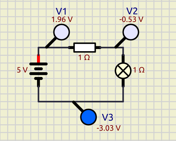
But I also said earlier that, if we don't look to be practical, the 0V reference could be virtual and anywhere. In fact, in your example, it is not even at any node.
In many places it is stated as "the law" that you MUST choose a node to be 0V, but indeed it is not absolutely true, maybe convenient, but you can do it without ground.
Some simulators will even give an error if there is no ground and others will complicate the code to force a random one to 0V.
On my side, I will keep doing what I used to by adding ground symbols, in isolated parts, at nodes that let the voltage readings on the simulated circuit be as friendly as possible (this is what I meant by practical).
Yes, that's a good idea imo.
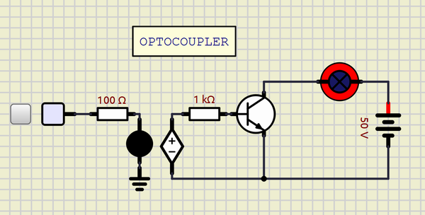
And the concept of "galvanic isolation" does not make a lot of sense in the simulation, this is just a bunch of numbers, there is no electricity here.
There are some things that might behave differently if you use grounds in 2 isolated circuits.
For example in the real world if you use a voltmeter between 2 isolated circuits you should read 0V, but that is because the voltmeter is indeed connecting the 2 circuits and forcing those nodes to be at the same relative potential because there is no return path.
In the simulation you only see this if you don't use grounds (at least in one of them) but this will not work with the oscilloscope for example, because the oscilloscope channels are not connected to reference pin (like real ones) they just "ask" the nodes what is their voltage, same thing with probes when you hover wires.
Real voltmeters or oscilloscopes rely on some current flowing to make a measurement. In the simulation, nodes just have a numeric value for it's voltage (and by definition it is always referred to 0) and you can just ask it for this value, no need to derive some current from it.

 Latest images


 GIGA_AMPS.zip
