Sorry for interrupting you.
It seems I wasn't clear enough in my previous post about the natural error warning (of the title).
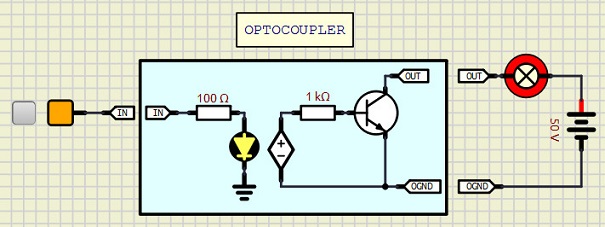
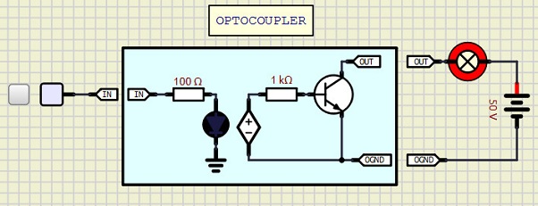
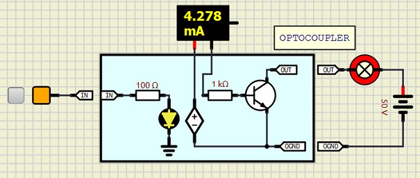
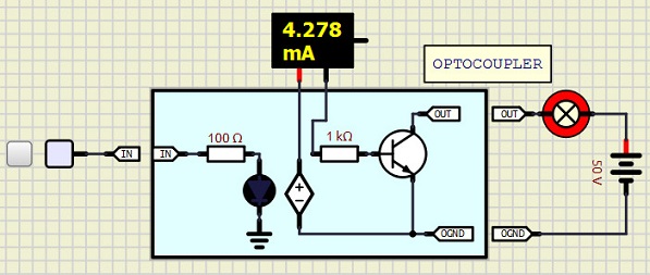
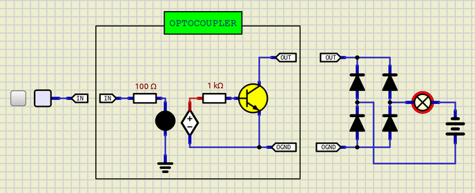
Let us assume that there will be no error message, in a future version of simulIDE. I wonder what will be the voltage value that will be shown by a voltage probe when it will be connected to the node OUT, for example, in the presented OP circuit. Could anyone know the answer?
I asked this because the voltage probe has to be referenced by the ground node (defined as 0V).
So, I guess, 'arcachofo' solved it, for this particular circuit, by adding a hidden ground node at one of the isolated part nodes, likely at the node labeled 0GND. Obviously, this will not be a global solution. I am afraid that a simulator needs to ask the user to add this ground node to where he sees more convenient to him (just for simulating the circuit, not in the real circuit).
Anyway, I may be wrong, and perhaps someone here knew another simulator which is supposed to work fine (no error warning) even if there is a part of the simulated circuit which is completely isolated and has, therefore, no ground nodes at all (not even one).

 Latest images


 OPTOCOUPLER_TEST.zip