Would you like to react to this message? Create an account in a few clicks or log in to continue.

You are not connected. Please login or register

GPIO Pins on Raspberry Pi

3 posters

Go down  Message [Page 1 of 1]

1GPIO Pins on Raspberry Pi Empty GPIO Pins on Raspberry Pi Sun Apr 04, 2021 4:42 pm

Aejwt


GPIO Pins on Raspberry Pi Img_2010

GPIO Pins on Raspberry Pi Img_2011

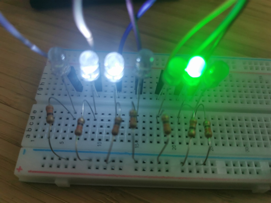
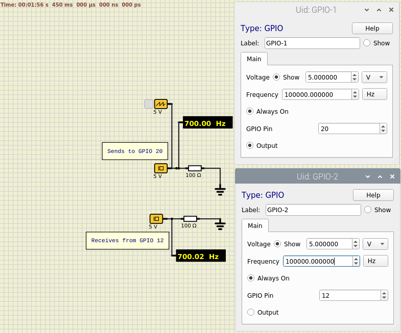
I downloaded and compiled SimulIDE-0.5.16-RC2 on Raspberry Pi 4 8GB with 64 bit Raspian. Then, I changed the source so that it can transfer binary data from simulation to physical GPIO pins of Raspberry Pi. (If voltage of a wire is less then 2.5V, output is 0. If it is greater than or equal to 2.5V the output is 1)

There are a few issues. Although the source code from Launchpad compiled without any warnings, program immediately exited with a segfault. I tried commenting different lines in main function, and it worked when I remove qInstallMessageHandler(myMessageOutput); line. I have not tried to solve this problem yet, just removed it. Therefore, there is no messages, and Rpi users will not be able to use latest code without changing it. This needs to be solved.

I edited probe component's code. (probe.cpp) Probes transfer signal every time their voltage get updated. Creating a new component with multiple pins is a much better idea, but I do not know how can I do this. I cannot even find where the component list is determined in source code.

There is only output from simulation. Input can also be easily done, but making it possible to change direction during simulation requires a lot of additional code. Now, modules are not working. I am going to try writing code for modules. It will check port registers of MCU and set direction of GPIO pins.

2GPIO Pins on Raspberry Pi Empty Re: GPIO Pins on Raspberry Pi Sun Apr 04, 2021 7:06 pm

arcachofo

arcachofo

This is interesting.

There are a few issues. Although the source code from Launchpad compiled without any warnings, program immediately exited with a segfault. I tried commenting different lines in main function, and it worked when I remove qInstallMessageHandler(myMessageOutput); line. I have not tried to solve this problem yet, just removed it. Therefore, there is no messages, and Rpi users will not be able to use latest code without changing it. This needs to be solved.
This Message Handler is indeed a fast and temporary solution to get the debug panel working.
So it will be removed soon.

And good to know that simulide compiles and run on RPi.


I edited probe component's code. (probe.cpp) Probes transfer signal every time their voltage get updated. Creating a new component with multiple pins is a much better idea,
Yes, I think a component representing RPi IO pins could be the best solution.

Being this feature exclusive for RPi I probably would do it as a plugin, not in the main project.
Or create an RPi build of simulide with this feature.

Aejwt likes this post

3GPIO Pins on Raspberry Pi Empty Re: GPIO Pins on Raspberry Pi Sun Apr 04, 2021 8:37 pm

Aejwt


I changed voltage source component. Voltage source gets input data from GPIO, and converts 1-0 input to 5V-0V voltage in circuit. There is a button connected to the input, and an LED connected to the output. When the physical button is pressed, the physical LED turns on. The wire between them is "virtual".

GPIO Pins on Raspberry Pi Gif10

I added an oscope to the circuit. Without filtering oscope does not show anything, but still measures frequency. I do not know the highest frequency it can measure. I can only generate 10 Hz by pressing the button quickly.  Smile I will test it after making a function generator using MCP4725 module.

Unfortunately, there is no internal ADC in Rpi. This is the main disadvantage of using Rpi as an Arduino or a different microcontroller.

The highest output frequency it can reach is approximately ~50 Hz using wave generator component. LED stops blinking above 70 Hz. Actually, it is possible to accurately generate Mhz frequencies on GPIO pins, but program is not real time. It is not a good idea to use SimulIDE for simulating high frequency output on Rpi.

4GPIO Pins on Raspberry Pi Empty Re: GPIO Pins on Raspberry Pi Sun Apr 04, 2021 10:43 pm

arcachofo

arcachofo

I added an oscope to the circuit. Without filtering oscope does not show anything, but still measures frequency. I do not know the highest frequency it can measure.
That is a bug after the last changes in Oscope.
I hope it will be solved soon.

Actually, it is possible to accurately generate Mhz frequencies on GPIO pins, but program is not real time. It is not a good idea to use SimulIDE for simulating high frequency output on Rpi.
You are right.

There are 2 different issues:

- Simulationis not in sync with real time, this is how it works internally:
There is a timer that by default runs at 20 cycles per sec. (50 ms).
Every time the timer is triggered, it launchs the circuit simulation which try to simulate 50 ms of "circuit time".
This circuit simulation runs on a parallel thread, in the menawhile the GUI is updated.

This means that the simulation try to keep circuit time at real time speed.
But it might take just a few ms or less to simulate the next 50 ms of "circuit time" depending on what is in the circuit.
So the simulation run in "batches".
The overall speed can be real time, but inside each "batch" it is not in sync with real time.

In your case: if there is only let's say 100 Hz square wave in the circuit, it takes very little to simulate 50 ms of circuit time.. let's say 1 ms.
So in the first ms the wave is gereated and the rest 49 ms the simulation just do nothing.


- Probe runs at "GUI speed", that is: by default it reads voltages every 50 ms.
Anything happening betwen each "sample" is not seen by the probe.

In 0.5.16 you can configure the speed of that timer:
- Open "Circuit Settings" and edit "Canvas Refresh" properties (by deault 20 FPS)
Maximum value is 100 FPS.

With this you can make the probe to take more samples.
But this can slow down simulation.

Aejwt likes this post

5GPIO Pins on Raspberry Pi Empty Re: GPIO Pins on Raspberry Pi Mon Apr 05, 2021 9:09 am

Aejwt


Increasing canvas refresh worked and it continued blinking LED connected to 100 Hz wave generator (at least, the LED did not turn off), but simulation speed dropped to 30%, so the output frequency was much less than 100 Hz. It also measured button frequency very wrong; showed values up to 40 Hz, which is impossible for me to generate by pressing a button.

6GPIO Pins on Raspberry Pi Empty Re: GPIO Pins on Raspberry Pi Mon Apr 05, 2021 6:08 pm

arcachofo

arcachofo

It also measured button frequency very wrong; showed values up to 40 Hz, which is impossible for me to generate by pressing a button.
I don't know how did you implement RPi_Pin->Simulide communication.
But in any case, as I commented in previous post, simulation execution is only in sinc with real time at low frequencies.

When you comunicate with the external world, the maximum reliable resolution you can get is the step of the mentioned timer, ussually 50 ms (if the computer can keep with that speed).

So you can use this for very low frequency stuff, not to pwm a led for example.

Think that simulide (or any other app) has no control over the resources of the computer all the time.
Is the OS that controls the computer and gives each app some execution time when it thinks is the better moment.

So, even if simulide tried to keep sinc with external world the maximum resolution it could get is the latency of the OS, which is typically of several ms.

There are some "workarounds" you could use, for example using the "Audio Out" component and connecting leds to the audio output (using some buffer).
This will still have a delay, but you could output a signal in the KHz range.

Aejwt likes this post

7GPIO Pins on Raspberry Pi Empty Re: GPIO Pins on Raspberry Pi Tue Apr 06, 2021 11:16 pm

Aejwt


I completely removed the previous GPIO code, which uses sysfs, and changed it with a better code that directly accesses registers using mmap and /dev/mem. Then, instead of using a GUI component like probe, I modified mosfet source code. When the gate voltage is higher than 1V, GPIO output is 1. If it is less than 1V, output is zero. Now, even Arduino PWM output is working. Brightness of the physical LED oscillates like it was connected to a real arduino output. Frequencimeter in circuit shows 492 Hz. Running too many programs at the same time makes the output visibly unstable, but this speed is enough for connecting any digital physical sensor to simulation.

GPIO Pins on Raspberry Pi Led10

Physlcal LED is looking even better than the LED in simulation.

arcachofo likes this post

8GPIO Pins on Raspberry Pi Empty Re: GPIO Pins on Raspberry Pi Fri Apr 09, 2021 7:57 pm

Aejwt


GPIO Pins on Raspberry Pi Circui10

Finally, there is both input and output. MOSFET component transfers its gate voltage to GPIO as 1-0, and clock component transfers 1-0 input from GPIO to simulation. In physical circuit, these two GPIO pins are connected with a 1K resistor, so it is supposed to read the same thing it writes.

Unfortunately, there is usually 0-5 Hz difference between the input and the output. The difference only stays zero when the frequency is one of these values: 100, 200, 400, 500, 1000. All of them divides both m_fps and m_timerTick, but I do not know why other values that are multiples of 50 and 20 do not work accurately.

The maximum usable frequency is around 800 Hz. Frequencies above that start to create ~5V at the output of difference amplifier.

Edit : 10 Hz, 20 Hz, 40 Hz, 50 Hz, 100 Hz frequencies are also produces exact frequencies. I realized after I had sent the post.

9GPIO Pins on Raspberry Pi Empty Re: GPIO Pins on Raspberry Pi Sat Apr 10, 2021 12:34 am

Aejwt


GPIO Pins on Raspberry Pi 1mhz10

I created a new component for GPIO pins using ClockBase class. (a weird "IO" is written on it  Smile ) I also created new two properties (pin direction and pin number) in component.cpp and component.h Now, it is possible to change pin number during simulation. It used to be a constant in the source code.

After setting the component's frequency (actually, it is still works like a clock, the only difference is its value being determined by GPIO) to 10 Mhz, it became able to show very high frequencies such as 1 MHz like in the screenshot.

I did not believe that it had actually created these frequencies on GPIO pins, so I wrote a separate C program to measure real frequency. That program showed extremely irregular values, from 5 kHz to 600 kHz. This obviously not accurate, but it is still good to see these values.

I realized that actually no frequencies are accurate on real pins. If I set wave generator to 10 Hz, it creates 2-20 Hz on pins. If I set it to anything above 1Mhz, it creates 200 kHz-700 kHz. The inaccuracy is terrible, and it is not even linear. However, the program measures the GPIO input with the same wrong timing, so the result is correct. This also means that it cannot measure an external square wave signal.

I was wrong about PWM. Error was unseeable because of the continuous change in the circuit I tried from examples. In another example circuit, where duty is constant, physical LED brightness looks vibrating and unstable. Average brightness is correct, but it is not stable.

10GPIO Pins on Raspberry Pi Empty Re: GPIO Pins on Raspberry Pi Sat Apr 10, 2021 5:45 pm

Aejwt


GPIO Pins on Raspberry Pi Compon10

The new component is done. It can both send and receive data from GPIO, and it is possible to change number and direction during simulation. Yesterday, I was still using MOSFET for output, but now no changes are required in other components.

GPIO pins 12 and 20 are physically connected with a 1K resistor. The frequency property determines the refresh frequency.

After solving some issues, I will start writing code for MCU registers.

11GPIO Pins on Raspberry Pi Empty Re: GPIO Pins on Raspberry Pi Sat Apr 10, 2021 6:03 pm

arcachofo

arcachofo

The new component is done. It can both send and receive data from GPIO, and it is possible to change number and direction during simulation. Yesterday, I was still using MOSFET for output, but now no changes are required in other components.
That is nice.

You can get almost consistent freq. readings whithin the simulation, because simulation is ovbiously  in sync with itself.

But the "external wolrd" will see things happening in "bursts" of activity determined by "FPS" Circuit property, followed by periods when nothing happens.  
Something like this:

GPIO Pins on Raspberry Pi Batche10

Each "burst" is happening every 50 ms (by default).
And they can be very variable in duration depending on what is in the circuit.

Aejwt likes this post

12GPIO Pins on Raspberry Pi Empty Re: GPIO Pins on Raspberry Pi Sat Apr 10, 2021 8:18 pm

Aejwt


GPIO Pins on Raspberry Pi Two10

Two simulations can communicate using a physical wire. I will do I2C tests this way before connecting real modules.

arcachofo likes this post

13GPIO Pins on Raspberry Pi Empty Re: GPIO Pins on Raspberry Pi Sat Apr 17, 2021 10:18 am

unbreakmyheart


its interesting, how did you managed to "changed the source so that it can transfer binary data from simulation to physical GPIO pins of Raspberry Pi."?

14GPIO Pins on Raspberry Pi Empty Re: GPIO Pins on Raspberry Pi Sat Apr 17, 2021 3:33 pm

Aejwt


unbreakmyheart wrote:its interesting, how did you managed to "changed the source so that it can transfer binary data from simulation to physical GPIO pins of Raspberry Pi."?

Actually, "changed the source" was not an appropriate explanation of what I did. The change is obviously not just adding a few lines of code, but it is also not really complicated. I used mmap function to map/access GPIO registers and ClockBase class for the new component I created. I am not sure if the ClockBase is suitable for this purpose, though. I will upload the source after completing it. The code still has some issues.

I have not had time to do anything related to this in the last few days.

Sponsored content


Back to top  Message [Page 1 of 1]

Permissions in this forum:
You cannot reply to topics in this forum