
 Latest images
SimulIDE-R1657_Win32
It seems it is just a display bug.
The maximum voltage of the orange channel (Ch 3) on the expanded scope (left side) is positioned downwards.
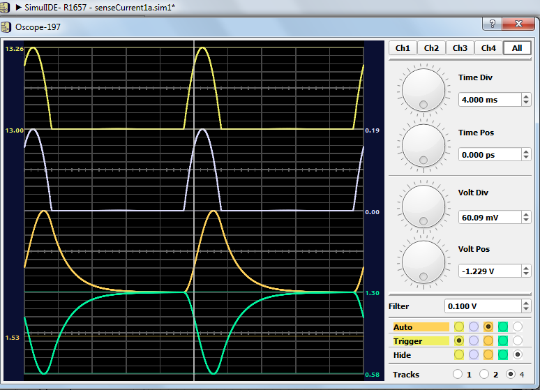
For instance, I added the x10 function to let the trace be seen properly; otherwise, the ‘auto’ doesn’t work as expected.
As a test, I also let the yellow channel (CH 1) to display the voltage on the two capacitors (both are connected to ground because this not the final circuit). There was no yellow trace even by using ‘auto’. But the scope cursor read its v(t) values correctly though it is invisible.
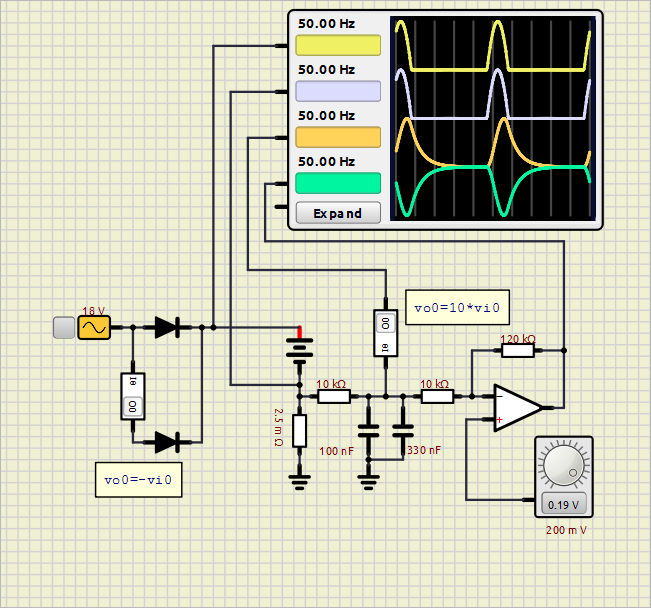
It seems it is just a display bug.
The maximum voltage of the orange channel (Ch 3) on the expanded scope (left side) is positioned downwards.
For instance, I added the x10 function to let the trace be seen properly; otherwise, the ‘auto’ doesn’t work as expected.
As a test, I also let the yellow channel (CH 1) to display the voltage on the two capacitors (both are connected to ground because this not the final circuit). There was no yellow trace even by using ‘auto’. But the scope cursor read its v(t) values correctly though it is invisible.
- Attachments
 senseCurrent1a.zip
 - You don't have permission to download attachments.
- (3 Kb) Downloaded 2 times


