Would you like to react to this message? Create an account in a few clicks or log in to continue.

You are not connected. Please login or register

New subcircuits for SimulIDE (v. 0. 4. 15 and higher)

+3
Tonigau
Mistral
Fizik_S
7 posters

Go to page : Previous  1, 2

Go down  Message [Page 2 of 2]

Fizik_S

Fizik_S

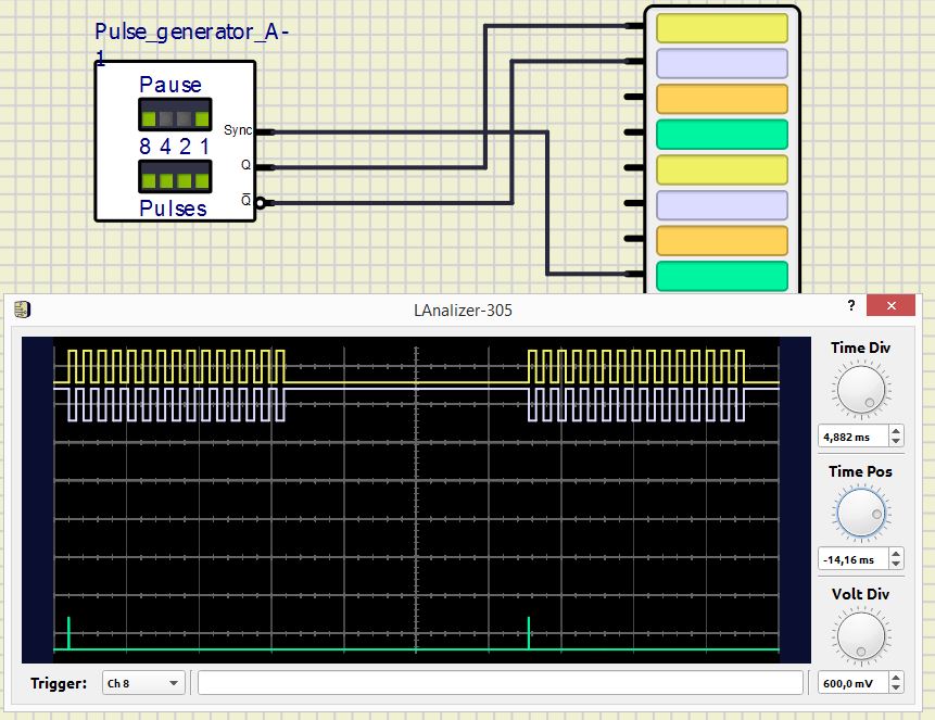
Modified the pulse generator a little.
Now it works in automatic mode and has a synchronization output.
A repeating sequence of pulse packs is removed from the generator output, the number of which in a pack is set by the binary code 1-2-4-8 from 1 to 15 pulses using the DIP switch "Pulses". Using the DIP switch "Pause", the duration of the pause between pulse packets is formed from 3 to 15 doubled pulse periods. Generator outputs: Q, !Q - direct and inverse generator outputs, Sync - synchronization output for an oscilloscope or logic analyzer.
Installation:
Unpack the attached archive "Pulse_generator_A.zip" to the Tools directory, to a file tools.xml add line:

Code:
<item name="Pulse_generator_A" folder="tools" info="AUTO Pulse generator (1-15 pulses)" />

The model for the SimulIDE 0.4.15 program

New subcircuits for SimulIDE (v. 0. 4. 15 and higher) - Page 2 Pulsea10


New subcircuits for SimulIDE (v. 0. 4. 15 and higher) - Page 2 Pulsea11
Attachments
New subcircuits for SimulIDE (v. 0. 4. 15 and higher) - Page 2 AttachmentPulse_generator_A.zip
You don't have permission to download attachments.
(11 Kb) Downloaded 11 times

Alex68 likes this post

Fizik_S

Fizik_S

The model of an automatic pulse generator for the SimulIDE 1.0.0 program.

New subcircuits for SimulIDE (v. 0. 4. 15 and higher) - Page 2 Pulsea12
Attachments
New subcircuits for SimulIDE (v. 0. 4. 15 and higher) - Page 2 AttachmentPulse_generator_A.zip
You don't have permission to download attachments.
(7 Kb) Downloaded 13 times

Alex68 and firefox66 like this post

Fizik_S

Fizik_S

After several unsuccessful attempts, I managed to make the TL494 model.
I do not guarantee full compatibility of the model with the original. Please test this model.
The model is designed for the program version R1452 and higher (trunk).

Installation:
unpack the archive to the directory "SimulIDE-R1452_Win64\data\" and add to the file "4-unsorted.xml" string:  
New subcircuits for SimulIDE (v. 0. 4. 15 and higher) - Page 2 494-310


New subcircuits for SimulIDE (v. 0. 4. 15 and higher) - Page 2 494-110
New subcircuits for SimulIDE (v. 0. 4. 15 and higher) - Page 2 494-210
Attachments
New subcircuits for SimulIDE (v. 0. 4. 15 and higher) - Page 2 AttachmentTL494.ZIP
You don't have permission to download attachments.
(7 Kb) Downloaded 13 times

Fizik_S

Fizik_S

I propose another model for building various power supplies: IR2153D - Self-oscillating half-bridge driver.

The model is designed for the program version R1452 and higher (trunk).

Installation:
unpack the archive to the directory "SimulIDE-R1452_Win64\data\" and add to the file "4-unsorted.xml" string:  
Code:

<item name="IR2153D" info=" Self-oscillating half-bridge driver" />

New subcircuits for SimulIDE (v. 0. 4. 15 and higher) - Page 2 Ir215310
Attachments
New subcircuits for SimulIDE (v. 0. 4. 15 and higher) - Page 2 AttachmentIR2153D.ZIP
You don't have permission to download attachments.
(7 Kb) Downloaded 4 times

Alex68 likes this post

Fizik_S

Fizik_S

When developing the IR2153 model, I made a mistake. The attachment contains a corrected model.
Attachments
New subcircuits for SimulIDE (v. 0. 4. 15 and higher) - Page 2 AttachmentIR2153D.ZIP
You don't have permission to download attachments.
(8 Kb) Downloaded 4 times

Fizik_S

Fizik_S

The model of the active button.
Generates a pulse (positive and negative) for the time of pressing the button.
You can assign a symbol to the button in the properties.
Installation: unpack the archive into the "Tools" directory, into a file tools.xml add a line:
Code:
 <item name="AButton" info="Active clock button" />
New subcircuits for SimulIDE (v. 0. 4. 15 and higher) - Page 2 Abt10
Attachments
New subcircuits for SimulIDE (v. 0. 4. 15 and higher) - Page 2 AttachmentAButton.zip
You don't have permission to download attachments.
(2 Kb) Downloaded 5 times

Alex68 likes this post

Fizik_S

Fizik_S

K176IE13.

The K176IE13 chip is designed to build a clock with an alarm clock and works bundled with K176IE12 (or a more modern version of K176IE18).

It contains on a chip: counters of minutes and hours, a memory register for an alarm clock, a circuit for comparing the current and recorded time, an audio signal generator. The counter K176IE13, having received the pulses of minutes, sequentially translates them into the binary code of the digits of minutes and hours and transmits them to an external decoder (usually K176ID2, K176ID3 or CD4056) for conversion into a seven-segment indicator code.
The chip was developed in the USSR.
Installation: unpack the archive to the "ICs" directory and add it to the file "ussr.xml " line:
Code:

  <item name="K176IE13" info="Counter for building a clock with an alarm clock" />

New subcircuits for SimulIDE (v. 0. 4. 15 and higher) - Page 2 176ie110
New subcircuits for SimulIDE (v. 0. 4. 15 and higher) - Page 2 176ie111
Attachments
New subcircuits for SimulIDE (v. 0. 4. 15 and higher) - Page 2 AttachmentK176IE13.zip
You don't have permission to download attachments.
(13 Kb) Downloaded 4 times

Alex68 likes this post

Fizik_S

Fizik_S

K176ID2, K176ID3

The K176ID2 and K176ID3 chips are designed to control a 7-segment LED, LCD or luminescendicator. The decoders K176ID2 and K176ID3 accept the four-digit code D3...D0 from 0000 to 1001 is "nine". Older combinations are not displayed. If a high level is applied to the input S, the chips transmit the input code to the indicator. At S = 0, the signal snaps and remains on the indicator.

The K176ID3 decoder differs from the K176ID2 decoder by open drains at the outputs. If you give "one" to pin M (pin 6), the output wires will work with an active zero: we switch on the LCD with a common anode. by grounding the pin M, we get active output high levels for servicing indicators with a common cathode

The high level applied to the input K extinguishes the indicator sign, the low level allows the indication. The output current of each segment should not exceed 9 mA.

The chip was developed in the USSR.
Installation: unpack the archive to the "ICs" directory and add it to the file "ussr.xml " line:
Code:
   
<item name="K176ID2" info="Cmos BCD to 7-segment LCD/LED driver with latch" />
<item name="K176ID3" info="Cmos BCD to 7-segment LCD/LED driver with latch, open Drain" />

New subcircuits for SimulIDE (v. 0. 4. 15 and higher) - Page 2 176id210
Attachments
New subcircuits for SimulIDE (v. 0. 4. 15 and higher) - Page 2 AttachmentK176ID23.zip
You don't have permission to download attachments.
(10 Kb) Downloaded 2 times

Alex68 likes this post

Fizik_S

Fizik_S

4-digit LED display with a common cathode for creating an electronic clock

Installation: unpack the archive to the "led_display" directory and add it to the file "led_display.xml" line:

Code:

    <item name="4bit_clock_cc"  info="4-Bit Led display for digital clock, com. cathode" />

New subcircuits for SimulIDE (v. 0. 4. 15 and higher) - Page 2 Led_cl10
Attachments
New subcircuits for SimulIDE (v. 0. 4. 15 and higher) - Page 2 Attachment4bit_clock_cc.zip
You don't have permission to download attachments.
(4 Kb) Downloaded 4 times

Alex68 likes this post

Fizik_S

Fizik_S

Logical symbols for MCS65xx.
Installation: unpack the archive into the data directory of the program.

New subcircuits for SimulIDE (v. 0. 4. 15 and higher) - Page 2 Mcs65x10
Attachments
New subcircuits for SimulIDE (v. 0. 4. 15 and higher) - Page 2 AttachmentMCS65.zip
You don't have permission to download attachments.
(4 Kb) Downloaded 5 times

arcachofo and Alex68 like this post

KarstenLehmann


Hi Fizik_S,
I like your components! GREAT JOB!
but sorry…
I don't get this to run… :-/ …found no example about it.
Please, do you have this ino- an sim1-file for me? (8digit-7segment)
best regards and thank you in advance!

New subcircuits for SimulIDE (v. 0. 4. 15 and higher) - Page 2 8bit10

Fizik_S

Fizik_S

KarstenLehmann wrote:Hi Fizik_S,
I like your components! GREAT JOB!
but sorry…
I don't get this to run… :-/ …found no example about it.
Please, do you have this ino- an sim1-file for me? (8digit-7segment)
best regards and thank you in advance!


Hello, Karsten Lehmann.

Thanks for the feedback.
The archive contains schemes for testing and control sketches for two types of displays: with a common cathode (8bit_led_cc_test.sim.sim1) and with a common anode (8bit_led_ca_test.simu.sim1). The diagram of the displays can be viewed in the post where these models are laid out. On the Internet, you can find more examples of using these displays.  

For example , http://domoticx.com/arduino-display-module-8x7-segmenten-75hc595/

New subcircuits for SimulIDE (v. 0. 4. 15 and higher) - Page 2 Test_210
Attachments
New subcircuits for SimulIDE (v. 0. 4. 15 and higher) - Page 2 AttachmentTest_LED_Display_8_Bit.zip
You don't have permission to download attachments.
(11 Kb) Downloaded 6 times

KarstenLehmann likes this post

KarstenLehmann


Hello Fizik_S,
THANK YOU VERY MUCH!
I tested this in the actual SR0. both examples (CA and CC) work on my ubuntu-linux.

The segments are a bit too dark. I have a look, if I find the reason…?!?
…any tipps…?

best regards and THANK YOU!

New subcircuits for SimulIDE (v. 0. 4. 15 and higher) - Page 2 7segme10

Fizik_S

Fizik_S

KarstenLehmann wrote:Hello Fizik_S,
THANK YOU VERY MUCH!
I tested this in the actual SR0. both examples (CA and CC) work on my ubuntu-linux.

The segments are a bit too dark. I have a look, if I find the reason…?!?
…any tipps…?

best regards and THANK YOU!


I see 2 ways to solve the problem:
1. In the sketch, increase the display time of each digit of the number. At the same time, the indicator may flicker
2. Change the settings of the indicator model

To do this, open the model diagram in the file explorer of the program. The screenshot shows the necessary actions. When the scheme opens, you need to change the property of the seven-segment indicator "Resistance". Reducing this parameter can increase the brightness of the display. After changing the parameter, the schema must be saved.

These actions can be done with other models.

New subcircuits for SimulIDE (v. 0. 4. 15 and higher) - Page 2 Displa12

KarstenLehmann likes this post

diego_souza


Hi everyone!

I wonder if someone has developed a subcircuit for the ADC0804 or similar:

https://pdf1.alldatasheet.com/datasheet-pdf/view/461614/TI1/ADC0804.html

The current ADC available on "Other Logic" doesn't have the "CS", "RD", "WR" and "INTR" pins, and these are necessary for the tests I want to make.

I'm thinking on trying to build the circuit below, but it is always nice to check if it was done before....

New subcircuits for SimulIDE (v. 0. 4. 15 and higher) - Page 2 Adc10

Thanks!

KarstenLehmann


Thank you, Fizik_S!
I will follow these points.

Fizik_S

Fizik_S

I have developed a new subcircuit: TIL311. This is a hexadecimal decoder with a transparent latch at the input and an LED display in one case.
Installation:
Unpack the archive to the directory "..\data\led_display\", to the file "led_display.xml " add a line:
Code:

  <item name="TIL311" info="Hexadecimal display wich logic" />

New subcircuits for SimulIDE (v. 0. 4. 15 and higher) - Page 2 Til31110
New subcircuits for SimulIDE (v. 0. 4. 15 and higher) - Page 2 Til31111
Attachments
New subcircuits for SimulIDE (v. 0. 4. 15 and higher) - Page 2 AttachmentTIL311.zip
You don't have permission to download attachments.
(9 Kb) Downloaded 5 times

Alex68, Defran, KarstenLehmann and RoVo like this post

Alex68

Alex68

Indicator and its applicationNew subcircuits for SimulIDE (v. 0. 4. 15 and higher) - Page 2 2023-248
New subcircuits for SimulIDE (v. 0. 4. 15 and higher) - Page 2 2023-249

RoVo likes this post

Fizik_S

Fizik_S

I bring to your attention new subcircuits for the simulator: LM3914, LM3915, LM3916.

These are the drivers of a linear scale built on LEDs. Subcircuits are not absolutely accurate. When cascading 2 chips in the "dot" mode, simultaneous illumination of 10 and 11 scale LEDs is possible. In the display mode of the glowing column, the subcircuit works correctly. The current passing through the LEDs is limited to 30 mA at any supply voltage and is not regulated. Subcircuits are designed for simulators version 1.1.0 and higher.  Tested in version Rev 2036.
Installation: Extract the contents of the archive to a directory "...\data\ICs\"  and add to the file "unsorted.xml" strings:

Code:
 <item name="LM3914" info="Dot/Bar Display Driver" />
  <item name="LM3915" info="Dot/Bar Display Driver" />
  <item name="LM3916" info="Dot/Bar Display Driver" />

New subcircuits for SimulIDE (v. 0. 4. 15 and higher) - Page 2 3914-110
New subcircuits for SimulIDE (v. 0. 4. 15 and higher) - Page 2 3914-210
New subcircuits for SimulIDE (v. 0. 4. 15 and higher) - Page 2 3914-310
Attachments
New subcircuits for SimulIDE (v. 0. 4. 15 and higher) - Page 2 AttachmentLM391X.zip
You don't have permission to download attachments.
(42 Kb) Downloaded 7 times

Alex68 and KerimF like this post

Alex68

Alex68

You can install this indicator!New subcircuits for SimulIDE (v. 0. 4. 15 and higher) - Page 2 2023-531
New subcircuits for SimulIDE (v. 0. 4. 15 and higher) - Page 2 2023-532

New subcircuits for SimulIDE (v. 0. 4. 15 and higher) - Page 2 2023-533


https://disk.yandex.ru/d/rGOLplFJdgInfQ

yabba235


Not work under R2056 and SR1 R1402. Any ideas what happens ?
Or use only R1452 version only (where I find *.exe file this version ?) ?
File "4-unsorted.xls" not exist, only "unsorted.xml" - create it ? Or use original ?
New subcircuits for SimulIDE (v. 0. 4. 15 and higher) - Page 2 Error11


Fizik_S wrote:After several unsuccessful attempts, I managed to make the TL494 model.
I do not guarantee full compatibility of the model with the original. Please test this model.
The model is designed for the program version R1452 and higher (trunk).

Installation:
unpack the archive to the directory "SimulIDE-R1452_Win64\data\" and add to the file "4-unsorted.xml" string:  
New subcircuits for SimulIDE (v. 0. 4. 15 and higher) - Page 2 494-310


New subcircuits for SimulIDE (v. 0. 4. 15 and higher) - Page 2 494-110
New subcircuits for SimulIDE (v. 0. 4. 15 and higher) - Page 2 494-210

Fizik_S

Fizik_S

New build at Rev 2068 uploaded in the new web site:
https://simulide.com/p/testers/

The problem has been solved in this version.

yabba235


Fizik_S wrote:New build at Rev 2068 uploaded in the new web site:
https://simulide.com/p/testers/

The problem has been solved in this version.

Yes, you right ! Now is working !

Sponsored content


Back to top  Message [Page 2 of 2]

Go to page : Previous  1, 2

Permissions in this forum:
You cannot reply to topics in this forum