Would you like to react to this message? Create an account in a few clicks or log in to continue.

You are not connected. Please login or register

SIDE 1226. BANER IN RED

2 posters

Go down  Message [Page 1 of 1]

1SIDE 1226. BANER IN RED Empty SIDE 1226. BANER IN RED Wed Jun 08, 2022 9:54 pm

Defran

Defran

The baner in red, I do not understand. In this simple scheme there are errors a lot without sense. I attach scheme and soft in construction.
Press operation, like a button (on_off) in order to see the simple circuit working...
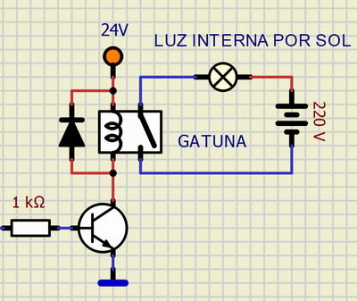
Randomlly it works, but not complitly ok. The lamps light with the contact open...

Windows 11.

SIDE 1226. BANER IN RED 2022-024
Attachments
SIDE 1226. BANER IN RED AttachmentLUZGAR.zip
You don't have permission to download attachments.
(7 Kb) Downloaded 1 times


Last edited by arcachofo on Sun Jun 12, 2022 2:10 pm; edited 2 times in total (Reason for editing : Mark as solved (green color))

2SIDE 1226. BANER IN RED Empty Re: SIDE 1226. BANER IN RED Wed Jun 08, 2022 10:54 pm

arcachofo

arcachofo

Looks like this is a problem with sockets, I will have a look.

By now you can try to disconnect all those sockets (anyway they are not needed).

3SIDE 1226. BANER IN RED Empty Re: SIDE 1226. BANER IN RED Wed Jun 08, 2022 11:15 pm

Defran

Defran

Yes, the sokets are problematics. They must be simply passive. Also I see problems with the transistor not in common emitter. I do the tests as you say. Also to Work with different voltages to 5V produces inconsistences some times.

In my scheme the sockes are necessary as a symbol to connect with modules, even if they are non-operative.

4SIDE 1226. BANER IN RED Empty Re: SIDE 1226. BANER IN RED Wed Jun 08, 2022 11:32 pm

Defran

Defran

Same thing, in general when diodes are included in serial in the circuits, failures of all kinds appear.

Saometimes, after restarting the computer, it works. It is like temporary data that allows it to work has been deleted...
Attachments
SIDE 1226. BANER IN RED AttachmentLUZ DE GARAJE_DEFRAN_c.zip
You don't have permission to download attachments.
(4 Kb) Downloaded 1 times

5SIDE 1226. BANER IN RED Empty Re: SIDE 1226. BANER IN RED Thu Jun 09, 2022 12:06 am

Defran

Defran

Now, with sockets, Restarting, loading the scheme and program, saving it and running, it works all the times. Is this a track?

6SIDE 1226. BANER IN RED Empty Re: SIDE 1226. BANER IN RED Thu Jun 09, 2022 12:48 am

Defran

Defran

Impossible. But in this case Redrawing and saving the problem disappears.

SIDE 1226. BANER IN RED Luz_de13

7SIDE 1226. BANER IN RED Empty Re: SIDE 1226. BANER IN RED Thu Jun 09, 2022 11:37 am

arcachofo

arcachofo

There are several issues here...

Maybe you invented a "free energy" device with that magic lamp.

In any case don't use sockets by now, there is an error.

8SIDE 1226. BANER IN RED Empty Re: SIDE 1226. BANER IN RED Thu Jun 09, 2022 12:52 pm

arcachofo

arcachofo

Issue with sockets solved at Rev 1235.
"Magic lamp" not solved yet.

I don't see any issue with transistors or diodes.
As far as I can see it is working correctly:
It is reading input 10 and turning ON/OFF "luz motor", which is doing correctlty.


Another issue is that you are connecting voltage sources to the output of those voltage regulators.
I don't think this will cause any problem, but it is not correct.

9SIDE 1226. BANER IN RED Empty Re: SIDE 1226. BANER IN RED Thu Jun 09, 2022 1:26 pm

Defran

Defran

arcachofo wrote:Another issue is that you are connecting voltage sources to the output of those voltage regulators.
I don't think this will cause any problem, but it is not correct.
Electrically it is ok and the advantage is less dissipation in the 78L05.

I have done it fisically many times for low powers. There are cases in which the cascade of regulatros is needed to go from high voltages to very low voltages.


Last edited by Defran on Thu Jun 09, 2022 2:02 pm; edited 2 times in total

10SIDE 1226. BANER IN RED Empty Re: SIDE 1226. BANER IN RED Thu Jun 09, 2022 1:40 pm

Defran

Defran

arcachofo wrote:I don't see any issue with transistors or diodes.
As far as I can see it is working correctly:
It is reading input 10 and turning ON/OFF "luz motor", which is doing correctlty.

Working in Simulide with bipolar transistors and diodes in circuits no common emitter, I had inconsistences and crashes. I´ll send to you cases, let me prepare them for you. Although the problem with the inconsistences is that sometimes they work, so I have to prepare cases in which environment they fail.

And... Remember in my case it is always under W11.

11SIDE 1226. BANER IN RED Empty Re: SIDE 1226. BANER IN RED Thu Jun 09, 2022 1:50 pm

Defran

Defran

But ("con tanta literatura") you do not explain to me the red baner meaning, which is very surprising...

12SIDE 1226. BANER IN RED Empty Re: SIDE 1226. BANER IN RED Thu Jun 09, 2022 2:09 pm

arcachofo

arcachofo

Electrically it is ok and the advantage is less dissipation in the 78L05.

I have done it fisically many times for low powers.
I don't understand why you use a 5V regulator if you already have a 5V voltage source.
In any case that is connected to nothing in the circuit.

Working in Simulide with bipolar transistors and diodes in circuits no common emitter, I had inconsistences and crashes.
Ok, I undestood that the problems were in this circuit.

But ("con tanta literatura") you do not explain to me the red baner meaning, which is very surprising...
That red banner means that the simulator could not resolve the circuit.

13SIDE 1226. BANER IN RED Empty Re: SIDE 1226. BANER IN RED Thu Jun 09, 2022 4:10 pm

Defran

Defran

In the real circuit that i will do in printed circuit, the controller (tiny84) will be supplied from this 5v. the rest wil be to 24 and 12 in the case of reciver.

in other words in the real live there it is not a simulide that supply the 5 v. This is the schematic previus to the printed circuit and I do not want to forget anything because all volts come from 24v (from 24... 12v and 5v.).

If this 5v confuse Simulide, I can remove it them.

Tempo with Tiny85...

SIDE 1226. BANER IN RED Esquem10

SIDE 1226. BANER IN RED Compon10

SIDE 1226. BANER IN RED Latera10

arcachofo wrote:Issue with sockets solved at Rev 1235.
.

Sockets solved, The best news.

14SIDE 1226. BANER IN RED Empty Re: SIDE 1226. BANER IN RED Thu Jun 09, 2022 6:17 pm

arcachofo

arcachofo

This is the schematic previus to the printed circuit and I do not want to forget anything because all volts come from 24v (from 24... 12v and 5v.).
That makes sense.

But what you are doing in simulide is equivalent to this:
Connecting a voltage source to the output of the regulator (same thing with 12 or 5 V).

SIDE 1226. BANER IN RED Esquem11

This makes more sense (and it will work):

SIDE 1226. BANER IN RED 011

If this 5v confuse Simulide, I can remove it them.
I think it does not have much effect (if the voltages are the same).
But it does not make sense to me and is useless.

15SIDE 1226. BANER IN RED Empty Re: SIDE 1226. BANER IN RED Thu Jun 09, 2022 7:43 pm

Defran

Defran

Yes. It is a mistake, at the output I should put a socket or a tunnel, yes. I change it in my scheme. Thanks.

16SIDE 1226. BANER IN RED Empty Re: SIDE 1226. BANER IN RED Thu Jun 09, 2022 8:52 pm

arcachofo

arcachofo

I'm sorry to announce that the recent discovery of the "free energy" lamp was an error and has ben solved at Rev 1237 (hopefully)

Not sure, but this could be the same issue with "free energy" transistors.

17SIDE 1226. BANER IN RED Empty Re: SIDE 1226. BANER IN RED Thu Jun 09, 2022 9:23 pm

Defran

Defran

I will test all new changes when you release the next
Simulide version. Thanks

Sponsored content


Back to top  Message [Page 1 of 1]

Permissions in this forum:
You cannot reply to topics in this forum