
 Latest images
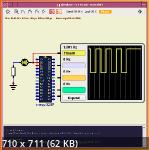
I make this schematic with:
- Generate wave form 1s (500ms delay for each low and high logic);
- No prescaler, nomarl mode;
- TCNT0 = 0xB2 (hex) = 178 (dec) -> that mean 78 (tick count to to 256 overflow) * 0.125 = 9.751 ms (close to 10ms)
- Make varLedCount to delay 50 x 10ms = 500ms -> Led blink() -> use oscilloScope to make sure the job done correctly.
Thanks arcachofo for his SimulIDE project.
Build on:
ArchLinux
SimulIDE 1.0.1 R1226,
CAVR
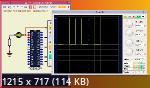


- Code:
/*******************************************************

Project : CAVR_Timer0_Prescaler1024_Led
Version : 1.0
Date    : 08/06/2022
Author  : Firefox66
Company : DIY
Comments:


Chip type               : ATmega328P
Program type            : Application
AVR Core Clock frequency: 8,000000 MHz
Memory model            : Small
External RAM size       : 0
Data Stack size         : 512
*******************************************************/

#include <mega328p.h>

// Declare your global variables here
unsigned int varLedCount = 0;

// Standard Input/Output functions
#include <stdio.h>
#include <delay.h>

// Define bitwise
#define _BV(bit)              (1<<bit)
#define setBit(sfr, bit)      (sfr |= (1<<bit))
#define clearBit(sfr, bit)    (sfr &= ~(1<<bit))
#define toggleBit(sfr, bit)   (sfr ^= (1<<bit))


// define led
#define LED_PORT  PORTD
#define LED_DDR   DDRD
#define LED_PIN   PIND
#define LED_BIT   0

void init(void){
      setBit(LED_DDR, LED_BIT);
      clearBit(LED_PORT, LED_BIT);
}


void ledBlink(void){
      toggleBit(LED_PORT, LED_BIT);
      //delay_ms(600);
}

// Timer 0 overflow interrupt service routine
interrupt [TIM0_OVF] void timer0_ovf_isr(void)
{
      // Reinitialize Timer 0 value
      TCNT0=0xB2;
      // Place your code here
      if(++varLedCount == 50){
            varLedCount = 0;
            ledBlink();
      }

}

void main(void)
{
// Declare your local variables here

// Crystal Oscillator division factor: 1
#pragma optsize-
CLKPR=(1<<CLKPCE);
CLKPR=(0<<CLKPCE) | (0<<CLKPS3) | (0<<CLKPS2) | (0<<CLKPS1) | (0<<CLKPS0);
#ifdef _OPTIMIZE_SIZE_
#pragma optsize+
#endif

init();


// Timer/Counter 0 initialization
// Clock source: System Clock
// Clock value: 7,813 kHz
// Mode: Normal top=0xFF
// OC0A output: Disconnected
// OC0B output: Disconnected
// Timer Period: 9,984 ms
TCCR0A=(0<<COM0A1) | (0<<COM0A0) | (0<<COM0B1) | (0<<COM0B0) | (0<<WGM01) | (0<<WGM00);
TCCR0B=(0<<WGM02) | (1<<CS02) | (0<<CS01) | (1<<CS00);
TCNT0=0xB2;
OCR0A=0x00;
OCR0B=0x00;

// Timer/Counter 0 Interrupt(s) initialization
TIMSK0=(0<<OCIE0B) | (0<<OCIE0A) | (1<<TOIE0);

// Timer/Counter 1 Interrupt(s) initialization
TIMSK1=(0<<ICIE1) | (0<<OCIE1B) | (0<<OCIE1A) | (0<<TOIE1);

// Timer/Counter 2 Interrupt(s) initialization
TIMSK2=(0<<OCIE2B) | (0<<OCIE2A) | (0<<TOIE2);

// USART initialization
// Communication Parameters: 8 Data, 1 Stop, No Parity
// USART Receiver: Off
// USART Transmitter: On
// USART0 Mode: Asynchronous
// USART Baud Rate: 9600
UCSR0A=(0<<RXC0) | (0<<TXC0) | (0<<UDRE0) | (0<<FE0) | (0<<DOR0) | (0<<UPE0) | (0<<U2X0) | (0<<MPCM0);
UCSR0B=(0<<RXCIE0) | (0<<TXCIE0) | (0<<UDRIE0) | (0<<RXEN0) | (1<<TXEN0) | (0<<UCSZ02) | (0<<RXB80) | (0<<TXB80);
UCSR0C=(0<<UMSEL01) | (0<<UMSEL00) | (0<<UPM01) | (0<<UPM00) | (0<<USBS0) | (1<<UCSZ01) | (1<<UCSZ00) | (0<<UCPOL0);
UBRR0H=0x00;
UBRR0L=0x33;

// Analog Comparator initialization
// Analog Comparator: Off
// The Analog Comparator's positive input is
// connected to the AIN0 pin
// The Analog Comparator's negative input is
// connected to the AIN1 pin
ACSR=(1<<ACD) | (0<<ACBG) | (0<<ACO) | (0<<ACI) | (0<<ACIE) | (0<<ACIC) | (0<<ACIS1) | (0<<ACIS0);
ADCSRB=(0<<ACME);
// Digital input buffer on AIN0: On
// Digital input buffer on AIN1: On
DIDR1=(0<<AIN0D) | (0<<AIN1D);

// Global enable interrupts
#asm("sei")

while (1)
      {
      // Place your code here

      }
}
- Attachments
 main.sim1.hex.zip
 - You don't have permission to download attachments.
- (2 Kb) Downloaded 5 times