
 Latest images

In a setup, we use two timer of the AVR 328 in order to drive a fullbridge (one TC per half bridge). There seem to be problems in handling the pin access once both timer are used.
Seen on V1.0.0. R815 WIN10
Situation 1:
This works fine. The problem appears, when step 5. and 7. is changed a bit:
Situation 2:
By this the toggling of PB3 and PB1 does not work all the time.
I made an example code for this:
I am somehow not able to upload pics. I get an "Uploaded file is not valid: exceeded image dimensions limit (image size : [849 x 86], limit : [1 x 1])." I attached all necessary files (pics, hex, code, sim1)
thanks
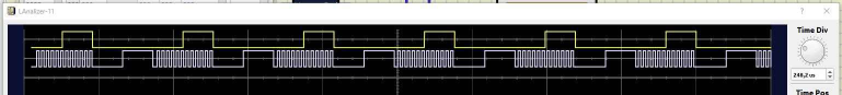
This is the correct one:
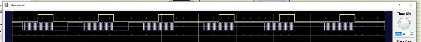
This one shows problems starting from the third repetition (lower signal does not show low between PWM, only high)
Seen on V1.0.0. R815 WIN10
Situation 1:
- Timer1 is initializes
- Timer2 not
- DDR register is set for both OCR Pins (B1 und B3)
- in the endless loop:
- turn on Timer1 (PB1 given by timer)
- toggle PB3
- turn off Timer1 (PB1 given by PORTB)
- toggle PB1
- repeat
This works fine. The problem appears, when step 5. and 7. is changed a bit:
Situation 2:
- Timer1 is initializes
- Timer2 not
- DDR register is set for both OCR Pins (B1 und B3)
- in the endless loop:
- turn on Timer1 (PB1 given by timer), turn off Timer2 (PB3 given by PORTB)
- toggle PB3
- turn off Timer1 (PB1 given by PORTB), turn on Timer2 (PB3 given by timer)
- toggle PB1
- repeat
By this the toggling of PB3 and PB1 does not work all the time.
I made an example code for this:
- Code:
#ifndef F_CPU
#define F_CPU 16000000UL
#endif

#include <avr/io.h>
#include <util/delay.h>
#include <avr/interrupt.h>


int main(void)
{
 TCCR1A = (1<<WGM10) ; //TC1 as Fast-PWM mode 8bit
 TCCR1B = (1<<CS10)  | (1<<WGM12); //no Prescaler
 OCR1A=128;

 //TCCR2A = (1<<WGM20) | (1<<WGM21) | (1<<COM2A1); //TC2 as Fast-PWM mode 8bit, Non Inverting
 //TCCR2B = (1<<CS20); // no Prescaler
 //OCR2A=128;

    sei(); //Global Interrupt Flag

 DDRB  = 0b00001010; //set PB1 and PB2 as output
    while (1)
    {
 //TCCR2A = TCCR2A & ~(1<<COM1A1); //uncomment this code
 TCCR1A = TCCR1A |  (1<<COM1A1); // Turn TC1 on  (PB1 set by Timer TC1)
 PORTB = 0b00000000; // clear PB3
 _delay_us(100);
 PORTB = 0b00001000; // set PB3
 _delay_us(100);
 //TCCR2A = TCCR2A |  (1<<COM1A1); //uncomment this code
 TCCR1A = TCCR1A & ~(1<<COM1A1); // Turn TC1 off (PB1 should be programmable with PORTB)
 PORTB = 0b00000000; // clear PB1
 _delay_us(100);
 PORTB = 0b00000010; // set PB1
 _delay_us(100);
    }
}
thanks
This is the correct one:
This one shows problems starting from the third repetition (lower signal does not show low between PWM, only high)
- Attachments
 TimerSimuHexPicsAndCode.zip
 - You don't have permission to download attachments.
- (46 Kb) Downloaded 1 times
Last edited by arcachofo on Wed Jan 12, 2022 3:26 pm; edited 3 times in total (Reason for editing : Set as solved (green color))
