Hi,
In this project, the code (written in AVR8 assembly) is rather a complex one (DSS_08_08.zip).
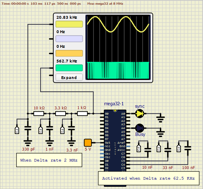
It generates sine waves by using delta modulation (Delta Sinewave Synthesis, DSS).
The advantage of this technique is that its hardware could be made simple (the reverse situation of Direct Digital Synthesis, DDS).
One MCU pin outputs a delta bit stream which, by using a simple RC filter, a sinewave is generated at its output.
The frequency is determined by the number of bits per cycle and the delta clock frequency (bit rate).
In this project, the lowest number of bits is chosen to be 96 and the highest 3088 bits.

Here, the MCU is ATmega32 running at 8 MHz.
With a bit rate of 2 MHz, frequencies between 20,833 Hz and 648.7 Hz are generated (there are 485 frequencies on their list).
And with a bit rate of 62,500 Hz (2MHz/32), the generated frequencies are between 651 Hz and 20.24 Hz (also 485 frequencies on their list).
These 970 frequencies have indexes from 0 to 969 (their complete list is attached below).
When the MCU gets a frequency index (by setting it before running the debugger, or perhaps via TWI, for example, on a real board), it generates internally the table (in SRAM) of the delta bit stream of the new requested frequency before it outputs it to the RC LPF.
Since I had to use only old versions of AVR Studio, LTspice and Excel (the only tools which I have the privilege to use in my designs lately) SimulIDE, version SimulIDE_1.0.1-R1386_Win32.exe, helped me discover/fix many bugs which were difficult to find/locate by AVR Studio.
Regards,
Kerim
Note: this code and sim1 are tested using SimulIDE_1.0.1-R1386_Win32.exe, I am not sure about other versions.
In this project, the code (written in AVR8 assembly) is rather a complex one (DSS_08_08.zip).
It generates sine waves by using delta modulation (Delta Sinewave Synthesis, DSS).
The advantage of this technique is that its hardware could be made simple (the reverse situation of Direct Digital Synthesis, DDS).
One MCU pin outputs a delta bit stream which, by using a simple RC filter, a sinewave is generated at its output.
The frequency is determined by the number of bits per cycle and the delta clock frequency (bit rate).
In this project, the lowest number of bits is chosen to be 96 and the highest 3088 bits.

Here, the MCU is ATmega32 running at 8 MHz.
With a bit rate of 2 MHz, frequencies between 20,833 Hz and 648.7 Hz are generated (there are 485 frequencies on their list).
And with a bit rate of 62,500 Hz (2MHz/32), the generated frequencies are between 651 Hz and 20.24 Hz (also 485 frequencies on their list).
These 970 frequencies have indexes from 0 to 969 (their complete list is attached below).
When the MCU gets a frequency index (by setting it before running the debugger, or perhaps via TWI, for example, on a real board), it generates internally the table (in SRAM) of the delta bit stream of the new requested frequency before it outputs it to the RC LPF.
Since I had to use only old versions of AVR Studio, LTspice and Excel (the only tools which I have the privilege to use in my designs lately) SimulIDE, version SimulIDE_1.0.1-R1386_Win32.exe, helped me discover/fix many bugs which were difficult to find/locate by AVR Studio.
Regards,
Kerim
Note: this code and sim1 are tested using SimulIDE_1.0.1-R1386_Win32.exe, I am not sure about other versions.
- Attachments
 DSS_frequencies.txt
 - You don't have permission to download attachments.
- (27 Kb) Downloaded 6 times
 DSS_08_08.zip
 - You don't have permission to download attachments.
- (17 Kb) Downloaded 8 times

 Latest images


