Would you like to react to this message? Create an account in a few clicks or log in to continue.

You are not connected. Please login or register

pic16f887 errors

2 posters

Go to page : 1, 2  Next

Go down  Message [Page 1 of 2]

1pic16f887 errors Empty pic16f887 errors Sun Oct 03, 2021 7:09 pm

chicodorea

chicodorea

I currently use SmulIDE 0.14.15 on Debian Linux 11 and the code is being generated on MPLAB X IDE v5.50 with XC8 compiler v2.32.

With the exception of fusebits, the code is summarized as follows:
Code:

#include <xc.h>
#include <pic16f887.h>

void __interrupt() myisr();

// Programa principal
void main(){
    // Configura registradores gerais
    ANSEL  = 0x00;
    ANSELH = 0x00;
    C1ON   = 0;
    C2ON   = 0;
    
    // Configura direcao e valores para entradas e saidas
    TRISB  = 0x03;
    TRISC  = 0x00;
    PORTC  = 0x01;

    // Configura OPTION_REG
    OPTION_REGbits.INTEDG = 1;

    // Configura interrupção externa
    INTCONbits.INTF = 0;
    INTCONbits.RBIF = 0;
    INTCONbits.GIE  = 1;
    INTCONbits.INTE = 1;
    INTCONbits.RBIE = 1;
    
    // Loop infinito
    while (1){
        // if (RB0==0) PORTD ^= 0b00000001;        
    }
}

// ISR
void __interrupt() myisr(){
    PORTC = 0b00000011;
    if(INTF){
        PORTC ^= 0b00000001;
        INTCONbits.INTF = 0;
    }
    INTCONbits.RBIF = 0;
}


The assembled circuit is shown in the following figure:
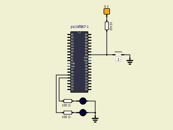
pic16f887 errors Pic16f10

The simulator does not execute the interrupt routine (ISR) when the button is pressed. However, it works perfectly when this same firmware is simulated on an equivalent circuit in Proteus.

I performed another test mounting another one similar to what I had done in Proteus and loading the firmware generated in MikroC PRO for PIC. This mount also did not work correctly in SimulIDE, not executing interrupts. At the moment the focus is on this mid-range PIC, PIC16F887 and I think some setting or option should be activated to enable interrupt recognition.

I've been using SimulIDE more intensively now because I'm helping to monitor the Microcontrollers course in the Electrical Engineering department at the Federal University of Sergipe, where I'm also a student.

I am fully interested in recommending the use of SimulIDE to my classmates, as it is light, fast, cross-platform and free. Thank you in advance for any support in solving this problem.


Last edited by arcachofo on Tue Dec 28, 2021 10:42 am; edited 5 times in total (Reason for editing : Marked as solved (green color))

2pic16f887 errors Empty Re: pic16f887 errors Mon Oct 04, 2021 2:30 am

arcachofo

arcachofo

Hi.
Interrupts should work in general, but could be errors in simulide.

I'm confused: you compile for 16f886, the MCU in the picture looks a 16f886, but it is labeled as 16f887, then you talk about 16f887.

Anyway I will have a look, I think the code should work in both models.

chicodorea likes this post

3pic16f887 errors Empty Re: pic16f887 errors Mon Oct 04, 2021 12:24 pm

chicodorea

chicodorea

You're right, I sent the wrong image, but this is the result of several attempts. For this reason the title has the designation 88x.

I edited the post to send with the mentioned chip. Thanks for the observation!

4pic16f887 errors Empty Re: pic16f887 errors Tue Oct 05, 2021 3:43 pm

arcachofo

arcachofo

Confirmed: it was an error in Ext INT pin.
PB2 was asigned instead of PB0.

Solved in Rev 249.

Thanks for reporting.

chicodorea likes this post

5pic16f887 errors Empty Re: pic16f887 errors Wed Oct 06, 2021 8:31 am

chicodorea

chicodorea

Thank you for your attention, speed, promptness and verification.

Actually, setting the INT to RB2 the interrupt works.
See the adapted circuit in the figure below.

pic16f887 errors Extern11

Code:

/*
 * File:  interrupt.c
 * Author: chicodorea
 *
 * Created October 1, 2021, 17:42
 * Revised October 6, 2021, 04:07
 */

#define _XTAL_FREQ 20000000UL

// PIC16F887 Configuration Bit Settings
// CONFIG1
#pragma config FOSC  = HS
#pragma config WDTE  = OFF
#pragma config PWRTE = OFF
#pragma config MCLRE = ON
#pragma config CP    = OFF
#pragma config CPD  = OFF
#pragma config BOREN = ON
#pragma config IESO  = ON
#pragma config FCMEN = ON
#pragma config LVP  = OFF

// CONFIG2
#pragma config BOR4V = BOR40V
#pragma config WRT  = OFF

// include files
#include <xc.h>
#include <pic16f887.h>

// function prototype
void __interrupt() myisr();

void main(){
    ANSEL  = 0x00;
    ANSELH = 0x00;
    C1ON  = 0;
    C2ON  = 0;
    TRISB  = 0x0F;
    TRISC  = 0x00;
    PORTC  = 0x01;
    OPTION_REGbits.INTEDG = 1;

    INTCONbits.INTF = 0;
    INTCONbits.GIE  = 1;
    INTCONbits.INTE = 1;
   
    while (1){

    }
}

// ISR
void __interrupt() myisr(){
    if(INTF){
        PORTC ^= 0b00000001;
        INTCONbits.INTF = 0;
    }
}


But I understand that the problem was fixed in revision 249, right?
can i download this review already?

6pic16f887 errors Empty Re: pic16f887 errors Wed Oct 06, 2021 10:54 am

arcachofo

arcachofo

But I understand that the problem was fixed in revision 249, right?
can i download this review already?
Yes, the issue is fixed in Rev 249: https://bazaar.launchpad.net/~arcachofo/simulide/simulide_0.4.14/revision/249

You can get the source code using bazaar:
Code:
~$ bzr branch lp:simulide/0.4.15
Or download the diff from the link above and apply patch.
Or apply the changes to the source code by hand (it's simple).
Then compile SimulIDE.

Or you can wait a few days and get builds from the dowload page: https://www.simulide.com/p/downloads.html
There is a critical bug about Arduino debugger, so downloads will be updated in a few days (including Rev 249).


Some links:
SimulIDE repository: https://launchpad.net/simulide
Commints in 0.4.15 branch: https://bazaar.launchpad.net/~arcachofo/simulide/simulide_0.4.14/changes
Commits in trunk (0.5.16) : https://bazaar.launchpad.net/~arcachofo/simulide/trunk/changes

7pic16f887 errors Empty Re: pic16f887 errors Thu Oct 14, 2021 8:42 pm

chicodorea

chicodorea

Hello my friend, look here again!

I have been using the PIC16F887 because it was chosen as a microcontroller for the academic discipline "Microcontrollers".
I'm currently migrating all the experiments that I developed using Proteus to SimulIDE, according to the semester's progress and topics of the subject under study at the University.

I feel very excited using and recommending this simulator, which is lean and efficient, beautiful and functional. Congratulations!

Now I have difficulties configuring the timer 1 interrupt, using C language from MPLAB/XC8 for Linux, can you help me?

I'll show you the code I'm working on and the circuit in simulation.

Code:

/*
 * File:   int_tmr1.c
 * Author: chicodorea
 *
 * Created on October 10, 2021, 9:08 AM
 *
 * MPLAB X IDE v5.50
 * XC8 v2.32
 * Gnome Shell 3.38.4
 * Debian 11 Bulleyes - 5.10.46-5 (2021-09-23) GNU/Linux
 * Linux 5.10.0.8-amd64 SMP
 *
 */

#define _XTAL_FREQ 20000000UL       // crysTAL FREQuency

// PIC16F887 Configuration Bit Settings
// CONFIG1
#pragma config FOSC  = HS           // Frequency OSCillator selection
#pragma config WDTE  = OFF          // WatchDog Time Enable
#pragma config PWRTE = OFF          // PoWeR-up Timer Enable
#pragma config MCLRE = ON           // Master CLeaR function Enable
#pragma config CP    = OFF          // Code Protection bit
#pragma config CPD   = OFF          // Data Code Protection bit
#pragma config BOREN = ON           // BrownOut REset SelectioN bit
#pragma config IESO  = ON           // Internal External SwitchOver bit
#pragma config FCMEN = ON           // Fails-safe Clock Monitor ENable
#pragma config LVP   = OFF          // Low Voltage Programming enable

// CONFIG2
#pragma config BOR4V = BOR40V       // Brown-Out Reset selection bit
#pragma config WRT   = OFF          // flash program memory self WRiTe enable bits

// include files
#include <xc.h>
#include <pic16f887.h>              // header file for PIC16F887

// function prototypes

// interrupt subroutine (ISR)
void __interrupt() myisr(){
    // timer1 interruption
    if(PIR1bits.TMR1IF==1){
        PORTC ^= 0b00001100;
        TMR1H = 0;
        TMR1L = 0;
        PIR1bits.TMR1IF = 0;
    }
}

// definition of global variables

// main program
void main(){
    // definition of local variable
    
    // variable initialization
    
    // general settings
    ANSEL  = 0x00;
    ANSELH = 0x00;
    C1ON   = 0;
    C2ON   = 0;
    TRISC  = 0x00;
    PORTC  = 0x00;
    
    // configuration of timer 1 and interruption
    PIR1bits.TMR1IF   = 0;
    TMR1H = 0;
    TMR1L = 0;
    T1CONbits.TMR1CS  = 0;
    T1CONbits.T1CKPS0 = 1;
    T1CONbits.T1CKPS1 = 1;
    PIE1bits.TMR1IE   = 1;
    INTCONbits.PEIE   = 1;
    INTCONbits.GIE    = 1;            // General Interrupt Enable
    T1CONbits.TMR1ON  = 1;
    
    // infinite loop
    while (1){
        if(TMR1H == 0x00 && TMR1L == 0x00){
            PORTC ^= 0b00000011;
        }
    }
}

pic16f887 errors Gifani10

What was missing to be included?
Where did I go wrong in the configuration?
Does command order make it impossible to interrupt?
I inserted a flag in the infinite loop and it's working, that is, timer 1 has been activated but this timer's interruption does not occur.

8pic16f887 errors Empty Re: pic16f887 errors Thu Oct 14, 2021 10:22 pm

arcachofo

arcachofo

Hi.
I think you are doing everything correctly. It's simulide which is doing wrong.

This issue should be solved at Rev 250.

I'm currently migrating all the experiments that I developed using Proteus to SimulIDE
My plan was to upload 0.4.15 with some fixes aroud Oct. 15.
But I see this device has many errors.
In adition I would like to improve some other stuff in this version, but some issues in next version are taking longer than I expected.
So I will delay the upload to the begining of November.

9pic16f887 errors Empty Re: pic16f887 errors Fri Oct 15, 2021 9:07 am

chicodorea

chicodorea

Got it, I'll wait then.
Until then!

10pic16f887 errors Empty Re: pic16f887 errors Fri Oct 15, 2021 4:51 pm

arcachofo

arcachofo

The good part is you have some more time to test.
And any possible issues could be solved before the release.

11pic16f887 errors Empty Re: pic16f887 errors Fri Oct 15, 2021 6:58 pm

chicodorea

chicodorea

Interrupts are important for subsequent experiments, especially timer interrupts.

Following the experiments, issues involving AD and EUSART conversion will be addressed. All of them effectively depend on the interrupts feature, whether to act on the AD converter interrupt or waiting for data on the serial port.

But I will work with exercises that deal directly with these peripherals without associating them with interruptions.
Then I will have done the tests I need.

I'm happy with your feedback!

12pic16f887 errors Empty Re: pic16f887 errors Fri Oct 15, 2021 8:20 pm

arcachofo

arcachofo

The last problem was specific for Timer1 overflow Interrupt.
Other interrupts should work, if not you can report them to get it solved.

13pic16f887 errors Empty Re: pic16f887 errors Sun Oct 17, 2021 9:10 pm

chicodorea

chicodorea

Of the timer interrupts, with the exception of Timer1, the others I have already tested and are working. This week I will test the AD converter and EUSART interrupts.

So, so far, I've only identified problems with the external interrupt, which has already been resolved, and the Timer1 interrupt that doesn't work.

14pic16f887 errors Empty Re: pic16f887 errors Wed Oct 20, 2021 12:01 pm

chicodorea

chicodorea

AD converter and AD converter interrupt tested and working correctly!

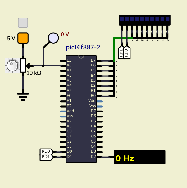
See the following example

pic16f887 errors Screen10

Code:

/*
 * File:   adc_int_example1.c
 * Author: chicodorea
 *
 * Created on October 20, 2021, 6:37 AM
 *
 * MPLAB X IDE v5.50
 * XC8 v2.32
 * SimulIDE 0.4.15 (September 13: Updated to SR7-Stable)
 * Gnome Shell 3.38.4
 * Debian 11 Bulleyes - 5.10.46-5 (2021-09-23) GNU/Linux
 * Linux 5.10.0.8-amd64 SMP
 *
 */

#define _XTAL_FREQ 20000000UL       // crysTAL FREQuency

// PIC16F887 Configuration Bit Settings
// CONFIG1
#pragma config FOSC  = HS           // Frequency OSCillator selection
#pragma config WDTE  = OFF          // WatchDog Time Enable
#pragma config PWRTE = OFF          // PoWeR-up Timer Enable
#pragma config MCLRE = ON           // Master CLeaR function Enable
#pragma config CP    = OFF          // Code Protection bit
#pragma config CPD   = OFF          // Data Code Protection bit
#pragma config BOREN = ON           // BrownOut REset SelectioN bit
#pragma config IESO  = ON           // Internal External SwitchOver bit
#pragma config FCMEN = ON           // Fails-safe Clock Monitor ENable
#pragma config LVP   = OFF          // Low Voltage Programming enable

// CONFIG2
#pragma config BOR4V = BOR40V       // Brown-Out Reset selection bit
#pragma config WRT   = OFF          // flash program memory self WRiTe enable bits

// include files
#include <xc.h>
#include <pic16f887.h>              // header file for PIC16F887

// definition of global variables
unsigned int num_adc;

// Interrupsion SubRoutine (ISR)
void __interrupt() myisr(){
    if(PIR1bits.ADIF){
        PIR1bits.ADIF = 0;
        num_adc = ((ADRESH << 8 ) | (ADRESL));
        PORTB = (num_adc & 0xFF);               // 8 bits LSB
        PORTD = ((num_adc>>8) & 0x03);          // 2 bits MSB
    }
}

// main program
void main(){
    // definition of local variable

    // variable initialization
    num_adc = 0;
    
    // general settings
    ANSEL  = 0x01;
    ANSELH = 0x00;
    C1ON   = 0;
    C2ON   = 0;
    TRISA  = 0xFF;
    TRISB  = 0x00;
    TRISD  = 0xF8;
    PORTB  = 0x00;
    PORTD  = 0XF8;
    
    // configuration of adc
    ADCON0bits.CHS   = 0x00;        // AN0     - channel selection
    ADCON1bits.VCFG0 = 0x00;        // Vdd     - vref+ voltage reference
    ADCON1bits.VCFG1 = 0x00;        // Vss     - vref- voltage reference
    ADCON0bits.ADCS  = 0x02;        // Focs/32 - conversion clock
    ADCON1bits.ADFM  = 0x01;        // Right   - justified A/D conversion result format select
    ADCON0bits.ADON  = 0x01;        // On      - enable adc module
    
    // configuration of adc interrupt
    INTCONbits.GIE   = 1;
    INTCONbits.PEIE  = 1;
    PIR1bits.ADIF    = 0;
    PIE1bits.ADIE    = 1;
    
    // infinite loop
    while (1){
        __delay_ms(1);
        ADCON0bits.GO = 1;                      // start conversion
        while(ADCON0bits.GO_DONE);
        PORTD ^= 0b00000100;
    }
}
Attachments
pic16f887 errors Attachmentadc_int_example1.zip
simu file
You don't have permission to download attachments.
(3 Kb) Downloaded 4 times
pic16f887 errors Attachmentadc_int_example1_xc8.zip
mplab xc8 c code file
You don't have permission to download attachments.
(2 Kb) Downloaded 3 times


Last edited by chicodorea on Wed Oct 20, 2021 1:01 pm; edited 3 times in total (Reason for editing : inserção do arquivo simu)

15pic16f887 errors Empty Re: pic16f887 errors Thu Oct 21, 2021 12:04 pm

arcachofo

arcachofo

Nice to know.
Thanks for reporting.

16pic16f887 errors Empty Re: pic16f887 errors Thu Oct 21, 2021 9:09 pm

chicodorea

chicodorea

It's important to point out that I haven't tested all the ports, because recently I saw other posts reported here reporting problems in the AN7 channel of the pic16f887 converter.

Because of this, I will expand the tests and report the results.

arcachofo likes this post

17pic16f887 errors Empty Re: pic16f887 errors Sun Oct 24, 2021 4:14 pm

chicodorea

chicodorea

Dear,

I was trying to set up an experiment with the PiC16F887 in SimulIDE and I came across difficulties in controlling pins RA4 and RA5. On the other hand, I configured the system for HS mode and I know that in this case I will not be able to control pins RA6 and RA7, destined for the 20 MHz oscillator crystal.

So what's going on with RA4 and RA5? is the HS mode affecting them too? do I have to change any parameters of the FUSE BITs? do I have to enable or disable something?

Follow the circuit and code.
Thank you in advance for the attention received.

pic16f887 errors Ports_10
Attachments
pic16f887 errors Attachmentports_example1.zip
Source code
You don't have permission to download attachments.
(2 Kb) Downloaded 3 times
pic16f887 errors Attachmentports_example1_simu.zip
SimulIDE file
You don't have permission to download attachments.
(3 Kb) Downloaded 2 times
pic16f887 errors Attachmentports.X.production.zip
HEX file
You don't have permission to download attachments.
(1 Kb) Downloaded 2 times

18pic16f887 errors Empty Re: pic16f887 errors Sun Oct 24, 2021 4:36 pm

chicodorea

chicodorea

I'm getting around these identified problems and moving on with the experiment. I will demonstrate here a typical experiment carried out at the University.

Goals:
1. That the student becomes familiar with the peripherals of the PIC16F887 (interrupts and timers)
2. Learn how to configure the proper registers to use external interrupts and timer interrupts.
3. Apply PIC16F887 interrupts and timers in motivating experiences, using 7-segment and LCD displays.
4. Be creative in implementing the experiences.

The system to be designed has the following components: 4x4 dot-matrix keyboard, 16x2 LCD and some other devices. Timer 2 interrupt will be used to scan the keyboard every 4 ms. With this keyboard, the duty cycle value (from 0 to 100%) and the frequency (1KHz, 1.5 KHz, 2KHz and 3KHz) of a signal that outputs through pin 0 of the E port will be programmed. Duty should remain unchanged when changing frequency, for example if duty cycle is 15% at 1 KHz, when changing to another frequency the duty cycle will remain at 15% and then you can change duty cycle to another value. The duty cycle value and the signal frequency must be displayed on the LCD.

(Antonio Ramirez, Ph.D.)

pic16f887 errors Lab2-210

It is important to note that this is the initial part of the system, as it has not yet been completed. I'm specifically talking about the source file.
Attachments
pic16f887 errors Attachmentkeypad_example1.zip
Source code
You don't have permission to download attachments.
(2 Kb) Downloaded 3 times
pic16f887 errors Attachmentkeypad.X.production.zip
HEX file
You don't have permission to download attachments.
(1 Kb) Downloaded 2 times
pic16f887 errors Attachmentexperimento_lab2-2.zip
SimulIDE file
You don't have permission to download attachments.
(5 Kb) Downloaded 2 times

19pic16f887 errors Empty Re: pic16f887 errors Mon Oct 25, 2021 10:55 am

arcachofo

arcachofo

So what's going on with RA4 and RA5? is the HS mode affecting them too? do I have to change any parameters of the FUSE BITs? do I have to enable or disable something?
As far as I know clock mode only affects RA6-7.

I don't think there is an error in your code.
By now I identified an error in simulide: RA4 is configured as open drain output, which is not the case in this device.
About RA5 I don't know yet why it is kept as input. I'm investigating this.

20pic16f887 errors Empty Re: pic16f887 errors Mon Oct 25, 2021 11:42 am

arcachofo

arcachofo

PORTA4-5 errors should be solved at Rev 253.

21pic16f887 errors Empty Re: pic16f887 errors Tue Oct 26, 2021 4:40 am

chicodorea

chicodorea

Does it have anything to do with comparators?

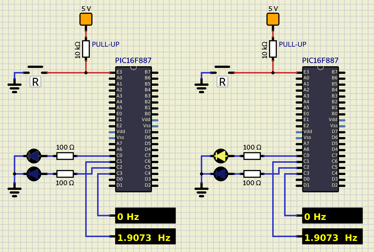
pic16f887 errors Pic16f11

22pic16f887 errors Empty Re: pic16f887 errors Tue Oct 26, 2021 9:00 am

arcachofo

arcachofo

Does it have anything to do with comparators?
Problem was not related with comparators.
RA4 was configured as Open Drain, which is the case for other devices but not for this one.
RA5 was configured as only input, which is the case for other devices but not for this one.

These issues are solved at Rev 253.

23pic16f887 errors Empty Re: pic16f887 errors Thu Nov 04, 2021 4:35 pm

chicodorea

chicodorea

I inform you that I recently managed to compile revision 253 and confirm that the mentioned issues have been remedied.

arcachofo likes this post

24pic16f887 errors Empty Re: pic16f887 errors Tue Nov 23, 2021 12:04 pm

chicodorea

chicodorea

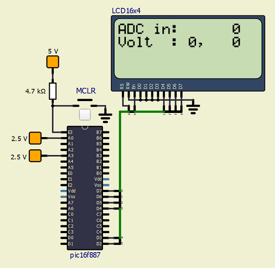
I believe there may be problems with Vref (+/-) on the PIC16F887's ADC, because when activated it doesn't work.

I'm talking about the adjustment in these bits:
ADCON1bits.VCFG1 = 0x00; // vref-
ADCON1bits.VCFG0 = 0x00; // vref+

Adjustment for internal voltage works
pic16f887 errors Fig111

and for external voltage does not work.
pic16f887 errors Fig211

25pic16f887 errors Empty Re: pic16f887 errors Wed Nov 24, 2021 3:18 pm

arcachofo

arcachofo

Hi.

I will have a look.

As I understand, in the secong image you are using VCFG0 = 1 and VCFG1 = 0 ??

Circuit and program files would help a lot.

Sponsored content


Back to top  Message [Page 1 of 2]

Go to page : 1, 2  Next

Permissions in this forum:
You cannot reply to topics in this forum